This thread has been locked.

If you have a related question, please click the "Ask a related question" button in the top right corner. The newly created question will be automatically linked to this question.

OPA657: OPA657 temperature characteristic

Part Number: OPA657
Other Parts Discussed in Thread: OPA857

Hi, support team

My customer has the questions as follow:

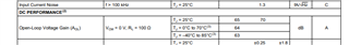
1. Could you provide OPA657 gain's temperature characteristic (0℃~40℃)?
(drift value across the temperature or graph vs temperature)

2. Could you provide OPA657 noise's temperature characteristic (0℃~40℃)?
(drift value across the temperature or graph vs temperature)


Thanks so much.

Best regards,
Yuki

  • Hello Yuki,

    I will work on getting your those curves.  If I have any questions or find we do not have certain data, I will update you.

    Best,

    Alec

  • Hello Yuki,

    The two curves you requested are not actually accomplishing what you would think: for the OPA657 (and many other devices) the gain drift & noise drift over temperature are not fully relevant figures.  Since the OPA857 is not a fixed-gain amplifier (it is open-loop and you can set your own gain), there is not a 'gain drift over temperature' as the amplifier will actively work to compensate any shift in gain via its feedback network: Rf -> Feedback resistor & Rg -> Gain Resistor; normally.

    So, to answer your two requested curves:

    1. As the OPA857 is not a fixed-gain amplifier, there will not be significant gain drift over temperature.  Specifically, the datasheet includes three values across a temperature range for Open-Loop Voltage Gain, with a TYP value of 70dB:

    This variance is very small across the temperature range of -40 to 85°C.

    2. Regarding the noise drift over temperature, the intrinsic noise present to the voltage & current noise of the amplifier are relatively low at Vn = 4.8nV/sqrt(Hz) & In = 1.3fA/sqrt(Hz) (also in figure):

    Instead, the resistor noise from the large feedback resistor, Rf, will dominate the noise in the circuit.  Resistor thermal noise, found described by the Nyquist & Johnson Thermal Noise equation & paper, will dominate an OPA657 circuit, especially over and across temperature.  TI has a document on Noise Analysis for High Speed Op-Amps which includes the resistor thermal noise (as a noise voltage):

    https://www.ti.com/lit/an/sboa066a/sboa066a.pdf

    The equation is sqrt(4*kB*T*R); temperature is in Kelvin, & kB is the Boltzmann constant k = (1.48±.07)×10−23J/K.  Here is a link to the original paper:

    https://web.mit.edu/dvp/Public/noise-paper.pdf

    I will work on a simulation to show how the OPA657 has relatively little noise at absolute zero, has more noise when the resistors contribute at 25°C, and how much noisier the amplifier is at 85°C.  For now, I hope this explanations help your understanding.

    Best,

    Alec

  • Hi Yuki,

    the gain drift depends on the set closed-loop gain and the open-loop gain and - because of this- is frequency dependent.

    Assume a normal low frequency OPAmp circuit. The open-loop gain stability is reported in literature to be about 1%/°C. By the help of negative feedback method the closed-loop gain stability is improved by the factor 1 / (1 + loop gain), where the loop gain is the open-loop gain divided by the closed-loop gain.

    Assume a closed-loop gain of 1V/V and an open-loop gain of 60dB at 10kHz. Then the loop gain is 1000V/V and the improvement factor is 1 / (1 + 1000). So the closed-loop gain drift is about 1%/°C x 1 / 1001 = 0.001%/°C. At increased frequencies the improvement factor degrades because of the decreasing open-loop gain and the gain drift degrades accordingly. Because of this the maximum signal frequency of application is usually very much lower than the bandwidth of OPAmp.

    That's how a low frequency OPAmp is working. With sufficient high open-loop gain very precise circuits can be built because then a huge gain reserve (= loop gain) is linearizing and stabilizing the circuit.

    A high frequency OPAmp circuit also uses the loop gain for linearization and stabilization, of course, but the focus is not so much on stability but more on speed! It's true that at low frequencies the gain drift can be as low as discussed above but in high frequency circuits the maximum signal frequency range of application can go up right to the bandwidth of OPAmp. In this region only very little loop gain is available and the gain drift can be rather high, much higher than in a precision low frequency OPAmp circuit as discussed above.

    What does this mean to you?

    The gain drift heavily depends on the actual circuit and it's impossible to present drift curves in the datasheet covering all applications. So you have to carry out gain drift measurements with the oven by yourself. And keep in mind that the gain drift will be frequency dependent.

    Kai