This thread has been locked.

If you have a related question, please click the "Ask a related question" button in the top right corner. The newly created question will be automatically linked to this question.

ALM2403-Q1: power dissipation minimization, is it necessary?

Part Number: ALM2403-Q1

Hello,

in my last post I got a answer for the additional 10nF in the reference design (SBOA504):

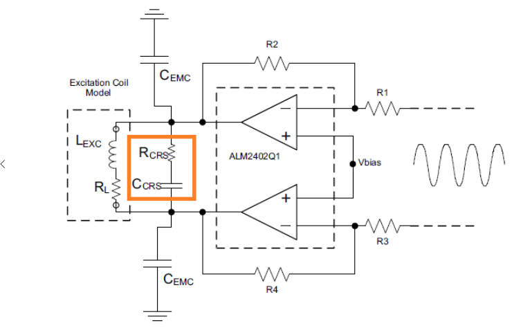
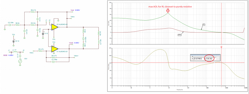
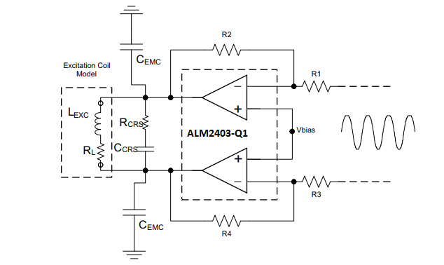
"In order to minimize the power dissipation inside the ALM2403-Q1, 10nF (Ccrs) capacitors are there to make the load look purely resistive. This is accomplished by canceling the complex part of coil inductance with addition of Ccrs caps while EMC capacitors between outputs and the ground may be added to help shield other devices on the PCB from the radiation created by the motor and resolver."


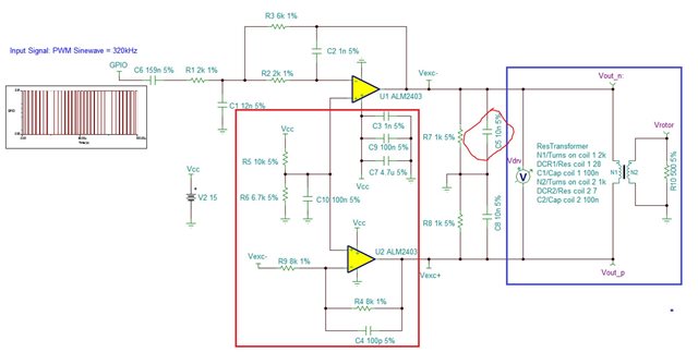
This additional 10nF really noised me, because I must put a additional serial 10Ohm to make the System stable, but with this 10Ohm then I got a another problem: reduced amplitude for resolver and very high power dissipation in case short fault.

So my question here is this 10nF on the output really necessary?

If yes, is this value "10nF" a general value for all cases or should be exactly calculated according to the resolver parameters? and how about the Rcrs? What is the "crs" meaning?

Here also my resolver parameter:

Primary side: R = 10 Ohm, L = 1.6mH @ 10kHz

Second side: R = 23 Ohm, L = 5mH @10kHz

Can anybody tell me what for a Ccrs or Cemc should I take? And why?

Thank you very much!

Jin

  • You do not have to use crs. The addition of RC network in resolver applications is used to reduce power dissipation and/or distortion in the op amp by aligning the voltage with current and thus making the effective load to be as close as possible to a purely resistive - this also improves stability of the circuit.

    The load compensation only works if ZC and ZL are tuned properly to cancel out their complex components at a given frequency. Placing a capacitor (or better a capacitor + resistor) in parallel with the resolver primary coil creates a parallel resonant tank - see https://www.electronics-tutorials.ws/accircuits/parallel-resonance.html

    Thus, the value of Ccrs is NOT fixed 10nF but instead MUST be calculated based of Lexc and resolver frequency,  fr.

    Here is the plan for tuning resolver complex load: 

    1. Measure the impedance of the resolver and the cable assembly (Lexc and RL) using the LCR meter. Use excitation frequency (10kHz) for the measurement.
    2. Since Zc=1/(2*Pi*f*C) while ZL=2*pi*f*L, in order to cancel their complex components, ZC=ZL, which means  1/(2*Pi*f*C) = 2*pi*f*L, resulting in fr=1/[2*Pi*sqrt(Lexc*Ccrs)]
    3. Calculate the value of the capacitor by solving the above equation for C­crs
    4. crs = 1/[(2*Pi* fr)^2*Lexc] where fr is the excitation frequency.  Thus, for Lexc=1.6mH at f=10kHz, Ccrs = 1/[(2*3.14*10e3)^2*1.6e-3] = 158.5nF. 
    5. Set Rcrs to RL (10ohm) for the initial testing, then experiment with its value to assure stability of the circuit.
    6. Cemc caps are used for EMI filtering and may not have to be added at this time
  • Hi Marek,

    thanks for the solution.

    I just tried this method and I got a amazing result, with the Ccrs and Rcrs, the System had a phase margin of 93.65 degree!

    This is even much better then the original simulation (62 degree) without any load in my last post! 

    How can it be possible? 

    And I noticed that the curve of Aol also very different then before, maybe here something wrong in Simulation again?

    here my simulation file.

    ALM2403-Q1_MFB_Test4.TSC

    cheers

    Jin

  • Jin,

    Actually, the phase margin is even higher but your lower op amp operates in a non-linear region as it is being driven to -2.7V (see below).

    In order to assure linear operation you MUST AC couple the input with C1 - see below - and only then you may perform valid AC stability analysis.

    Doing so shows the actual phase margin of 138 degrees - see below.  The effective load is virtually purely resistive at 10kHz.

    Conducting a transient analysis shows a very stable system with the small-signal overshoot of just 10% - see below.

    ALM2403-Q1_MFB_ AC Stability.TSCALM2403-Q1_MFB Transient Stability.TSC

  • Hi Marek

    Thanks for your support. But there is still a problem, why the AOL changed so much?

    If you compare your old simulation, you can see the big difference, it looks more like the curve in datasheet.

    The newest result from AOL can't match the datasheet. Actually, Aol curve shouldn't be changed, because it's the inherent property of a OPA and independent of the periphery, correct?

    and here also a snapshot from ALM2403-Q1 datasheet to compare:

  • Jin,

    AOL has changed because in the latest circuit instead of grounding the load, you apply Vout2 signal that is 180 degrees out of phase that increases the effective load - see below.  A heavier output load means lower gain of the output stage, which leads to a lower AOL.

    If you ground the new load, you will get back to AOL of 117 dB and 62 degrees phase margin - see below.

  • Hallo Marek

    So now I got 2 different Aol and phase margin, are the both correct?  Which value should I take?

    BR

    Jin

  • Yes, since AOL is a function of load, you get two different loaded AOL's for two different loading conditions.  Both AOL and phase margin are correct for given configuration - thus, you should use AOL that goes together with the respective configuration.  Regardless, they both result in stable operation.

  • Hi Marek,

    now I'm confused, Aol is the open loop gain of OPA, so it's a inferent atrribute, it should be independent of the load.

    So why did you say "since Aol is a function of load"??

    BR

    JIn

  • Jin,,

    This is not correct - AOL is a strong function of output load.  An open-loop gain is a product of gains of all internal op amp stages.  If for example the op amp has three stages and all of them have dc gain of 100 with RL=10k, the overall open-loop dc gain would be AOL=100*100*100=1,000,000, or 120dB. The first two stages "see" only fixed load (so their gain does not change) but the last stage may be loaded with different load - the heavier the output load (lower value resistor) the lower the gain of the output stage resulting in the lower overall open-loop gain. Thus, in our previous example the output stage gain could get lower from 100 down to 10 for the overall AOL = 100*100* 10=100,000, or 100dB.  This is the reason why for RL=10k AOL of ALM2403-Q1 is 111dB but for RL=225ohm it's 104dB - see below.

    Now, in your application the load changes dynamically as the low side of the complex load, Vout2, instead of being fixed (grounded) moves 180 degrees out of phase with respect to the top signal, Vout.  At around 10kHz resonant frequency the load compensation causes cancelation of the complex components (ZL and ZC) making the load purely resistive - this results in the lightest RL and thus highest AOL (see below).

  • Thanks for the reply!

  • No problem.  Good luck!