Other Parts Discussed in Thread: INA210-215EVM, INA190, INA186
Hi,
I have a few questions concerning the INA211 current sense amplifier.
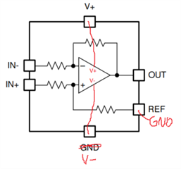
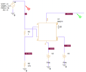
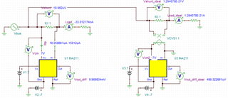
First, I am assuming here that the GND pin is the negative rail voltage pin of the op-amp (see attached drawing). If it is the case, why isn’t the GND pin called something like V-? Still assuming that GND is for the negative rail, in an application where I need to sense a sinewave (alternating current), can I put the GND pin to the negative supply of a bipolar source, like it my example below? That way my output voltage can be bipolar, which is what I want ideally.
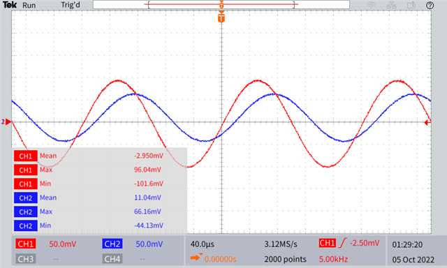
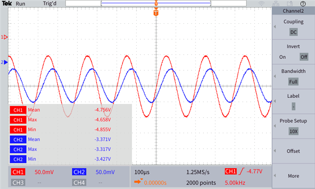
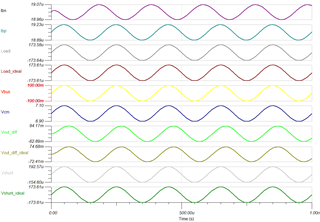
In the datasheet we can read that in order to work in a “bidirectional configuration”, the REF pin should be connected to a reference voltage and that the output voltage is going to be biased upwards by that reference level, but when I do so (in Pspice), everything goes well when my current flows from IN+ to IN- but in the opposite direction, the output voltage offset as well as the gain is very strange (I can’t make sense of it).
My last question is: What does a “bi-directional” current sense amplifier means? Does it only mean that the component can be used in a High-side or Low-side configuration? Or does it mean current can flow both ways, meaning I can sense alternating current that goes below and above my reference, which is GND? Because if it is the case, the Pspice simulation suggests otherwise.
I hope I explained it well enough, I can provide more details if needed.
Thanks in advance,
