I have prototyped up the attached circuit using the OPA2348 and am wondering if you can help me understand the results I am getting.
Conditions:
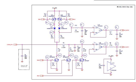
- CONN_PIN is unconnected
- SEL0 = 0V
- SEL1 = 0V
- SEL2 = 5V
- SEL3 = 0V
The above conditions turn on only PFET Q2-B. All other pull-up and pull-down sources are disabled.
Results:
- Node CONN_PIN is 4.761V
- Node N1 = 4.763V
- Node N2 = 4.757V
- Node N3 = 4.972V
- Node N13 = 4.758V
- Node N21 = 4.969V
How come the op-amp rails with an input voltage within the common mode range? If I start adding a little bit of load (e.g. 1 Meg from CONN_PIN to ground), the output of the op-amp is within a few millivolts of the input to the op-amp.