This thread has been locked.

If you have a related question, please click the "Ask a related question" button in the top right corner. The newly created question will be automatically linked to this question.

OPA656: Floating inputs and output

Part Number: OPA656

Hello,

My customer was using a few different configurations of a PCB and had a situation where the passives around the OPA656 (R2, C10, and R5) were not populated, but the device was populated and supplied with ±5V. On one board they noticed ~80mA being drawn from the negative 5V supply rail. They are concerned this could cause issues on more boards, could damage the device, and might even cause issues on the negative rail if a catastrophic short fault could occur. 

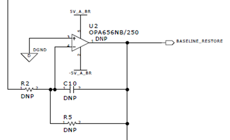
I am guessing that even just a little bit of noise on the negative terminal would cause the output to drive open loop as hard as possible and could result in current limiting and heating up. I am asking for more information about what load is present on "BASELINE_RESTORE" and will let you know what I find out, but in the meantime, wanted to get your feedback. 

It looks like if they put a 0Ω in R5, it would connect the negative terminal to ground through another 0Ω resistor in the circuit. Would that be the proper way to handle an unused device? Ground both inputs? 

Thanks,

John

  • Inputs should never float (as you've seen).

    The simplest way to handle an unused opamp is to configure it as a voltage follower, with the input voltage somewhere in the valid common-mode range. This is indeed what you get with pin 3 at 0 V and R5 populated (with any value).

    Also see The Unused Op Amp—what to do?

  • Hi John,

    if the OPAmp U2 is still in use and is not "unused", you could mount a dummy "R5" and dummy "C10" with "R5" being 10...20 times the expected original R5 and C10 being 1/10...1/20 of the expected original C10. This would allow the circuit running stably and still offer the possibilty of populating components later.

    Kai

  • Thank you both for the quick reply. I have reiterated the need to not leave inputs floating but the engineer is asking some additional questions since it seems that there are populated boards with this floating configuration.  Output of the amp seems to be floating - no load. 

    What is the current limit of the device? I see that the datasheet shows 70mA typical but doesn't specify anything like a limit.

    They measured 9.48mA on +5V and 84mA on -5V.  They are asking what we think the variation could be and if this could damage the device and possibly cause a short circuit fault on a power rail. My guess is that there will be device to device variation that could vary quite a bit and that we are likely not able to guarantee how a device might catastrophically fail. But if you have any comments on that, please let me know. 

    Lastly, since this is likely a noise coupling issue, couldn't the current be "flipped"? Where the output could drive the opposite way and they might see higher current on the positive rail as opposed to the negative rail? 

    Any advice on the above is greatly appreciated.

    John

  • Figure 25 shows that 70 mA is the short-circuit current.

    The supply current or quiescent current is defined as the current that flows into +VS and out of −VS. Any difference is the load current.

    It appears that the output is shorted to the positive supply. As far as I can see, there is nothing wrong with this state, as long as you stay inside the 1 W power limit.

  • Hi John,

    I ask myself how the 84mA of the -5V supply did run through the OPA656, if there isn't anything connected to the output of OPA656 or to its -input. The current can only flow through the +input of OPA656 then, from signal ground to the -5V supply voltage pin?

    It would be interesting to know where exactly the 84mA is running through the circuit...

    Kai

  • Hi Kai, I was wondering the same thing. Like it it was oscillating and just charging and discharging some parasitic capacitance or if this is a constant DC current. Will find out more. Thank you both! Appreciate the help thinking through this. 

    John

  • Hi Kai and Clemens,

    Sorry for the delay, just got more feedback from the engineer with a clear final question:

    Can TI help us analysis this?

    • This device has positive input terminal grounded, and the negative input floating.
    • The negative inputs is picking up a max of 200mV noise from other signal lines (the noise amplitude and shape is stable as the noise source signals are stable)
    • The output is grounded through a 0Ω resistor.

    So even though this circuit is in the open-loop high gain amplifying mode, due to the grounded output, the open-loop op-amp is limited to the current saturation of the device ~75mA. Across 5 boards, the OPA656 op-amp gets warm but hasn't been damaged.

    Junction temperature calculation estimation: use measured data from one board, chip case temperature max 50C, -5V measured -3.8V 84mA, +5V measured +4.9V 10mA, use simulation data 72uV 75mA for 0V output, then Tj=50C+(3.8V*84mA+4.9V*10mA+72uV*75mA)*140.8=101.9C, <150C absolute maximum rating.

    Are we able to comment on whether the device could get damaged in this situation? Attached is the periodic noise signal that gets coupled to the negative terminal's floating traces (blue trace is the inverting input):

    Thanks,

    John

  • Your calculation is correct. The OPA656 will be fine. (The power supply obviously is not happy.)

  • Thanks! Yeah, they put a 10Ω in series with the amplifiers supply rails. 

    John

  • Hi John,

    I'm not so optimistic. If several boards were involved in this barbecuing, there's no guarantee that the other boards had not to suffer from higher short-circuit currents. Also, measuring the temperature of an OPAmp case is no good methode to determine the die temperature because the epoxid chip case is no good heat conductor. It can easily happen that the metallic tip of temperature sensor is cooling down the chip case at the measuring point and that a way too low case temperature is measured.

    Also, the thermal resistances given in the datasheet are only valid for optimized layouts with unhindered air convection. In many applications the real thermal situation is way worse and higher die temperatures are observed.

    Ok, hopefully the involved OPAmps have survived this short-circuit period. But because the die temperature is even under optimistic assumptions above 100°C, longer lasting short-circuit conditions will decrease the life time of OPAmp. So, in any case, the customer should remove the short-circuit at the output of OPAmp and mount suited dummy resistors arround the OPAmp to make it work properly without being short-circuited or oscillating.

    Sorry for my private opinion, but delivering boards with an OPAmp that is short-circuited at the output is pretty idiotic in my eyes.

    Kai