This thread has been locked.

If you have a related question, please click the "Ask a related question" button in the top right corner. The newly created question will be automatically linked to this question.

INA180B3IDBVR output saturated

Other Parts Discussed in Thread: INA180

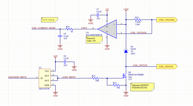
+VDC is 24 VDC. A solenoid is connected to COIL_VOLTAGE and COIL_SWITCH.  COIL_CURRENT_SENSE goes to an A/D converter in a microcontroller. SOLENOID_DRIVE is from the PWM output of the microcontroller. The PWM algorithm is working very well but the output of the current sense amplifier VOUT is 5V regardless of the current in R13. What am I doing wrong?

  • Hi Randall,

    the free wheeling diode shut sit directly across the coil. In the way you have mounted it an insane voltage drop can occur across the shunt eventually even destroying the INA180.

    Also, connect a decoupling cap of sufficient capacitance from the left side of shunt to the source of NMOS and keep all the tracks of the switching elements (except the coil, of course) close to the INA180. This means: The grounds of U3, M1, U4 and of the decoupling cap should sit very close to each other, otherwise layout inductances may cause additional destroying inductive kick backs.

    Slowing down the switching speed by increasing R15 can additionally help. Another advantage of increasing R15 is the reduce of charge injection into the gate source capacitance of M1. With a steep edge coming from U3 a huge amount of switching noise will be injected into the ground line causing ground bounce, unwanted ground voltage drops and inductive kick backs.

    And because the INA180 is probably already damaged, take a fresh INA180.

    Kai

  • Hi Randal,

    You mentioned VOUT is 5V regardless of the current in R13, does it include the case where PWM is inactive and the MOS switch is off? In this situation, there should be zero current and VOUT should be essentially zero volts. But are you measuring 5V?

    Also how many boards have you tested? Are they all behaving the same?

    Regards, Guang

  • Hello Guang, yes, when the solenoid is disconnected, VOUT is still at 5V. I have only tested one board.

  • Hi Randal,

    I would inspect the board for potential soldering or connection issues, probing the INA180 pins to make sure input/ground etc are as expected.

    Another note, there are two pin out options, A and B, for this device and the packages are identical. Is there a possibility that the board layout is for one while the other was installed accidentally?

    Regards, Guang

  • Hello Guang, I've tried another board with a resistive load and it is working properly. I'll investigate a transient failure as Kai suggested.

  • Hi Randal,

    Good to know that you eliminated some other suspects and can concentrate on one. Please notify us what you’re able to find out. Meanwhile I’ll close the thread for now, but you’ll still be able to post here with updates.  

    Regards, Guang