This thread has been locked.
If you have a related question, please click the "Ask a related question" button in the top right corner. The newly created question will be automatically linked to this question.
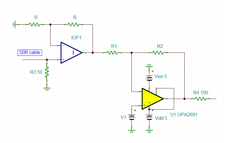
I am designing a high speed amplifier using the OPA2691 in an inverting topology. Upon initial use, the op amp was drawing 100+mA of current on both the positive and negative supplies. The op amp is being supplied with +/- 5V. I was originally seeing on an oscilloscope that the op amp was oscillating with no input connected. After resolving this issue and no longer having the op amp oscillating, the current being drawn was about 60mA. The test bench set up was with no input, no load, and no oscilloscope probes connected (to not have the added capacitance). The datasheet says that quiescent current is 10.2mA. I was wondering if there is anything I am overlooking or any solutions to reduce this amount of current being drawn. Any help would be great, thank you!
Hello Mike,
Could you share your schematic and/or board files for your circuit?
I would like to verify your setup; detailed information will help me quickly assess the behavior you have observed.
This current-feedback amplifier can output high currents (190mA) and source or sink the current. Understandably, a 60mA current draw without a load is not ideal.
Please send over an update with more details when you have a moment.
Best,
Alec
Here is a schematic of my circuit:
When conducting the quiescent current test, I disconnected the load to C5 and R3 as well as disconnected the input on the Vin node. The non-inverting input terminal was grounded. Here is a picture of the breadboard that I have set up:
This application is for driving a silicon array with Super Lattice LEDs on it, so it will be a high capacitance load. I have a pi model of the silicon chip, but for this preliminary testing I was using a dummy load of C5 and R3.
Almost certainly oscillating with that high of supply current, your output RC bandlimits at 53MHz, might be higher F. you could try scope probing with a >200MHz path on the power supply pin looking for a low level oscillation there.
Hello Mike,
Thank you for sharing your circuit information. Michael's point is true; please attempt to use his advice on probing the circuit. I will take a deeper look into your schematic and reply with my thoughts.
Best,
Alec
Hi Mike,
well, the circuit isn't optimal but should run stably:
I see the main issue in your setup. A breadboard is not suited to handle a 280MHz current feedback OPAmp. Look only at the supply voltge decoupling: The decoupling caps are too far away from the chip and the ground leads suffer from huge wiring inductances. This cannot work.
You could fabricate a central ground star point on your tiny printed circuit board and connect the ground terminals of all components of your circuit to this central ground star point. This would not be as good as using a solid ground plane but far better than what you have right now.
Then, you should use such a ground spring when probing:
And do not connect any OPAmp's input or output pin directly with the scope probe without inserting a suited isolation resistor (47...100R).
Kai
The reason I was using a breadboard is because the PCB that was created was originally oscillating with the circuit on the board, so I tried to create a more basic circuit on the breadboard to try and get some better results. I went back to the PCB and with no input connected the current being drawn on the power supplies are about 9 to 10 mA of current. On the board there are SMB connectors to connect the input of the op amps to an AWG, when the cables were connected to the input and to the AWG (but leaving the AWG turned off) the current being drawn jumps to 35mA on the positive supply and 4mA on the negative supply. Is this due to a termination issue?
Also, is powering this op amp with an asymmetrical supply (possibly one of +7V and -3V) a viable option or does this op amp need a symmetrical supply?
Schematic of PCB: note that C19, C22, R20, and R6 are not populated. R2 and R4 are also not populated.
Picture of PCB:
Probing the output of the op amp when the inputs are connected to the AWG (again, not turned on though) this is the output on the scope:
There is a DC offset on the output (even though the non-inverting input is grounded) of about 3.3V. I am not sure why the signal is offset on the output when the virtual ground is 0V and no other DC signal is being injected into the circuit.
All of this testing was done with +/- 5V supplies.
Hi Mike,
when doing with HF OPAmps and using cables you should use the well established 50R (or 75R) technique. This means that the cable has to be properly terminated at both ends with the cable impedance. A 50R cable must see a 50R driving resistance and a 50R load at the receiving side, e.g..
In your case you connect the cable loosly to R3 which means that the feedback loop of OPAmp is extended over the whole cable and that a complex impedance (cable impedance) is inserted in the feedback loop. A HF OPamp is not working this way and quits this with oscillation or instability.
A remedy could be that you add an additional OPAmp only for purpose of receiving the signal from the cabe and driving the input of U2. By this the feedback loop of U2 would no longer see the complex cable impedance but would be driven low ohmically by the cable receiver.
Kai
Hi Kai,
This is my first time designing a HF op amp circuit so I am still learning and really appreciate the help that you have been providing so far. The AWG I am using has a driving resistance of 50R, the cable I am using has an impedance of 50R, and on the PCB R1 and R3 are 50R resistors in series with the input. I even tried replacing R2 and R4 with 50R resistors to ground but that made the problem worse. When R2 and R4 were 50R, the current being drawn with no input connected was 38mA for the + supply and 3mA for the - supply.
What do you mean by the cable is loosly connected to R3? I figured having the 50R resistor in series with the input would be the termination resistance the cable needs to see but it seems that is not the case. Adding a 50R resistor to ground from the input also doesn't help so what am I doing wrong with the termination?
Mike
Hi Mike,
for a proper cable termination of a 50R cable at the receiving end the 50R termination resistor must provide exactly 50R and this for all frequencies, even frequencies far exceeding the bandwidth of OPAmp. But this would only work with an ideal OPAmp. Unfortunately, the OPA2691 is no ideal OPAmp and is not able to maintain a 50R input impedance at all frequencies. Because of this It's way better to connect the receiving end of a 50R cable to the +input of OPAmp with a 50R resistor mounted from the +input to signal ground.
What do you mean by the cable is loosly connected to R3?
A cable is not simply a piece of wire but a very complicated arrangement of complex (L and C) impedances. Because of this a cable within the feedback loop of an OPAmp can destabilize the OPAmp. See the schematic below:
On the left an ideal sitauation is shown without any cable between the AWG and the OPAmp. (The AWG is a voltage source in series with R7, omitted here for clarity.) Only true resistances are in the feedback loop of OPAmp and the OPAmp will behave properly.
On the right the situation is shown with a cable between the AWG and the OPAmp. (The AWG is a voltage source in series with R5.) The feedback loop no longer consists of true resistors but now the complex cable impedances L1, L2, L3,... and C1, C2, C3, C4, ... are within the feedback loop and can destabilize the OPAmp.
Cables are mostly a problem in HF-circuits with HF-OPAmps, because then the Ls and Cs begin to become "alive" and to form resonances resulting in ringing, echoing, etc. At low frequencies (and with slow OPAmps !), on the other hand, a cable looks like a simple capacitance and its impact on stability can usually be compensated by a phase lead capacitance in the feedback loop.
Kai
So I understand transmission lines and dealing with reflections from classes that I have taken, I was able to reduce the current being drawn but not get it under quiescent. When the AWG is off, the current drawn on the + supply is 34mA and 4mA on the - supply. When the AWG is on the current drawn on the + supply drops to 20mA and on the - supply it is 6mA. So I am definitely getting closer but the + supply is still above quiescent. I can't find any oscillation in the circuit. With a handheld FLIR camera I do see that the input resistors are warming up, so there is definitely current being drawn through those resistors and they are getting as hot as the op amp. I do have the 150R resistor to ground connected to the input, do I need to change the value of this resistor?
It is strange because yesterday when I powered everything on it was working properly, the current drawn was around quiescent. Today it is drawing more current. I know that small changes can lead to big differences in HF, but the inconsistency is tripping me up.
Hi Mike,
I cannot find the decoupling caps C13, C14, C16 and C17 on your printed circuit board. Please show a photo of your layout.
Kai
Here is the layout of the board:
The decoupling caps are on the bottom layer of the board so they can be as close to the component as possible. The ground plane is on the bottom layer (this is a 2 layer board) with cutouts where the op amp pads are as the datasheet says to do. The value of the decoupling caps were 22uF and 1uF. I also tried a 1uF and 0.1uF pair to see if that helped reduce current draw but it didn't.
I want to bias this op amp to adjust the offset of the output signal, I was doing this by having the non-inverting input connected to a DC voltage of 1.4V. I have noticed though that when the positive input is grounded the current drawn is under quiescent. I tried incrementally increasing this voltage and found that when the voltage gets to above 300mV the current drawn on the + supply goes above quiescent. Can I not bias the op amp by putting a DC voltage on the non-inverting terminal? I know for voltage feedback op amps this is a possible way, but this is my first time working with a current feedback op amp. Does the non-inverting terminal have to be grounded?
Hi Mike,
you can do this with a current feedback amplifier too. The current drawn on the + supply increases because the output voltage of OPAmp will also rise and current is flowing through the feedback resistors to signal ground. Keep in mind, though, that the OPA2681 has huge input bias currents which can result in big voltage drops when you generate the offset voltage by the help of resistive voltage dividers.
Mike, I don't see the one big mistake in your schematic and layout but many little mistakes which in combination can also result in instability and weird performance. Unfortunately, you have managed the OPA2619 like a (standardly slow) OPAmp but not like a 280MHz OPAmp providing an ultra high slew rate of 2100V/µs. This makes giving help a challenge here.
I tell you now how I would improve the layout:
All the signal traces are too long. This especially means the copper tracks from the SMA connectors to the OPAmp circuit. The connectors must directly sit at the OPAmp circuit, or at least the 50R termination resistors. Also, move the both inputs tracks away from each other and have a ground fill between them which you connect to the undelaying ground plane which lots of vias.
But also the feedback resistors must sit closest to the pins of OPAmp.
Let me show you an example layout which I have drawn for another thread to enlighten what I mean:
I would remove R20, C603, C19, C24 and R24. And R21 by replacing it by a short circuit. Then I would move R1 and R22 closest to the OPA2691. See the example above. If you want to terminate the cable by R1=50R then I would remove R2, otherwise you will get a mistermination.
My simulations show that R22 should be increased from 140R to 300R and that R23 should be increased to at least 56R (better more). Also move R23 closest to the OPA2619, directly (!!!) to the output pin of OPA2619. Every millimeter counts!
Then, I would place the vias away from the solder pads. Otherwise during the soldering solder tin can flow into the vias, away from the solder pads.
I would connect all the decoupling caps C13, C14, C16 and C17 to the solid ground plane, not only C13.
Take care: When you connect two ceramic caps in parallel for the decoupling, nasty resonances can occur when using uneven capacitances. The reason for that is that ceramic high caps do not show any relevant ESR required for the dampening. Because of that the datasheet recommends the use of a polarized 6µ8 cap (best tantal). A tantal shows enough ESR to provide sufficient damping. If you don't want to use a tantal, removing the smaller decoupling cap help. But if you keep both ceramic caps in parallel, the parallel circuit becomes very high ohmic at the resonance frequency, completely loosing all its decoupling abilities. Guess at what frequency the OPAmp will oscillate...
Also, decoupling caps must sit on the same plane as the OPAmp, otherwise the inductance of vias will add too much parasitic inductance. See the example above.
I think these are the most important measures to be taken to make the circui properly work.
Kai
Also of importance is the use Pi-filters in the supply voltage decoupling. In the above example this is done by C1, R1 and C2. You can also add a ferrite bead in series to R1 and decrease R1 then to a couple of Ohms. I never use HF-OPAmp without Pi-filters in the supply voltage lines!
Kai
And completely remove the cables from the inputs during the testings, especially if the AWG is turned-off and the sender sides of cables aren't properly terminated. Connect a 50R resistor instead directly from the left side of R1 to signal ground, if you want to simulate the connected AWG.
Connect the cables only when the circuit is doing well without the cables. Divide and conquer
Kai
Kai, thank you so much this is very helpful feedback!
Should the Pi-filters also be placed as close to the power pins as possible, or can they be further away? I am asking because I am trying to design an amplification board to amplify 64 analog signals, so I am trying to think of scalability. This first board was just to get 2 signals amplifying by the 1 op amp and then scale up from there. If the SMA connectors cave to be as close to the input as possible, then how would this be feasible for having 32 op amps on a single board? Is there a way to design the circuit so the input signal can travel across a longer PCB trace so the op amps can be laid out as compact as possible? For example, could I lump the PCB trace into the same transmission line as the input cable and terminate based on that 'new' T-line?
I am going to make those changes that you suggested for this board first. I am just curious because my ultimate goal is to design this same circuit for 64 signals. I know that makes it a lot trickier so any suggestions would be greatly appreciated!
New problem occurring, I am powering the op amp with +7V and -3V and when the non inverting input is connected to anything above what seems like a diode threshold above the negative supply (0.5 to 1V) there was almost 100mA of current being drawn when powered on. It seems like either the ESD protection diodes got turned on somehow or a gate got ruptured and I can't figure out how or why. The non-inverting input is not behaving as expected or as it should. This problem has happened multiple times and I don't understand how this has occurred. The op amp never received above 30mA of current and running for no longer than 40-60 seconds. So, I don't think that the component would have burned out so I am confused as to how and why this keeps happening. Any help would be greatly appreciated!
Hi Mike,
the Pi-filter should be mounted as close as possible to the OPAmp, while the cap directly sitting on the supply pin is of special importance. The Pi-filter once installed this way fully isolates the global supply line from the OPAmp. This means that the OPAmps do no longer see each other over the common supply voltage line. When using several HF-OPAmps hanging on the same supply voltage line using Pi-filters is a must, at least from my experience.
The termination resistor and the OPAmp must sit closest to the SMA conenctor. This is how HF-OPAmps have to be handled. Period (). Anything else will reuslt in disaster.
I recommend to not connect the cable into the feedback loop but to the +input of suited HF-OPAmp as shown below:
The input voltage on the inputs of OPAmp must never exceed the supply voltages, not even briefly. This is also and especially valid for the power-up and power-down period. You can try to insert a current limiting resistor (R26 in your schematic?) to limit the current to below 30mA. But adding current limiting resistances at the input of a HF-OPAmp is always critical and can result in decreased stability.
Kai
So if I am understanding correctly, have the input cable immediately hit the termination resistor and a buffer and from there I can route the signals to where I need to on the board? Also in your schematic I am assuming you are parallel terminating the cable with that 50R resistor to ground correct?
In regards to the biasing voltage on the non-inverting input, I didn't put a voltage larger than the negative supply and it was behaving like this. Could it be due to the board issues you mentioned before or do I need a current limiting resistor like you said?
Hi Mike,
So if I am understanding correctly, have the input cable immediately hit the termination resistor and a buffer and from there I can route the signals to where I need to on the board?
Yes, the input cable must immediately hit the termination resistor and the OPAmp input. Anything else would result is a mistermination and possibly ending in echoing and ringing. And no, from there you cannot simply route the signals to where you need to on the board. In HF every copper track is a transmission line (whether unwanted or wanted) and you have to use impedance matching, at least at the sending side. You can route the copper track by using the microstrip or stripline technique:
https://www.protoexpress.com/blog/difference-between-microstrip-stripline-pcb/
https://en.wikipedia.org/wiki/Transmission_line
Having said this, echoing and ringing becomes the more relevant the longer the copper track and the faster the signal becomes. The best way to keep things simple is to avoid longer copper tracks at all and to mount the HF-OPAmps with their inputs and outputs as close as possible to each other.
A perfect circuit has all HF-OPAmps sitting close together so that each output connects imediately to the following input. Have the SMA connectors close to the receiving and sending OPAmps. If the signal has to travel a longer distance use a 50R cable which is properly terminated at both ends.
In regards to the biasing voltage on the non-inverting input, I didn't put a voltage larger than the negative supply and it was behaving like this. Could it be due to the board issues you mentioned before or do I need a current limiting resistor like you said?
Keep in mind that C12 can carry a destryoing charge when the supply voltage of OPAmp is suddenly removed. Then, C12 discharges into the +input of OPAmp and can destroy the chip, if the current is not limited. Because of that: If you have to experiment with an OPAmp, do not suddenly apply or remove the supply voltage but use a power supply which is able to ramp up and down with a limited slew rate, so that all the voltages in the circuit can settle in time without ever exceeding the supply voltage.
Kai
Thank you for those links, they were very helpful!
I added the current limiting resistor as you suggested and with no input it is under quiescent current! However, I am still having the issue of when there is an input the current jumps to above quiescent. I think this could be because of the termination issue you mentioned before. So I have two questions.
How could I test that the input cable is being driven in the feedback loop of the op amp to confirm that there is a miss-termination causing the transmission line to be part of the feedback loop?
The fastest signal I am sending into this op amp is 10MHz. Now I know this is not a super fast signal, but should I still be treating this as high speed design? And I should still be making the changes you suggested before even though I am below 50MHz?
Hi Mike,
The fastest signal I am sending into this op amp is 10MHz. Now I know this is not a super fast signal, but should I still be treating this as high speed design? And I should still be making the changes you suggested before even though I am below 50MHz?
it's already HF only because you use a HF-OPAmp. Even if you only plan to handle plain DC voltages, your project is a HF-application because you use a HF-OPAmp. Keep in mind that there's always HF-noise in your circuit coming from the feedback resistors, the OPAmp itself or from the input signal and that there's always voltage step changes caused by the power-up ramping of supply voltage which will introduce HF-contents into the signal chain, even if you only plan to manage DC voltages. And from these unwanted HF-contents oscillation can arise at any time, if your circuit is instable.
How could I test that the input cable is being driven in the feedback loop of the op amp to confirm that there is a miss-termination causing the transmission line to be part of the feedback loop?
You can try to measure the voltage at the -input of OPAmp. But this only works if your scope probe doesn't introduce any relevant stray capacitance. You can try to insert an isolation resistor for the scope measurement, but this will introduce an unwanted low pass filtering so that you may not see what's actually going on.
Another way is to run a simulation which includes the behaviour of cable:
Mike, doing with HF-OPAmps can tend to become rocket science and I can only heavily recommend to keep things as simple as ever possible. Even if you follow well estabilshed design rules in your HF-circuit you will be confrontated with a couple of "bad" surprises. But if your approach is based on "hope" because you design too complicatedly and leave the path of wisdom you may run into endless distaster.
When doing HF follow the KISS principle: "Keep it simple, stupid!"
Kai