Observing anomalous behaviour on the output of INA240A3 and A2, and grateful for all help and insight.
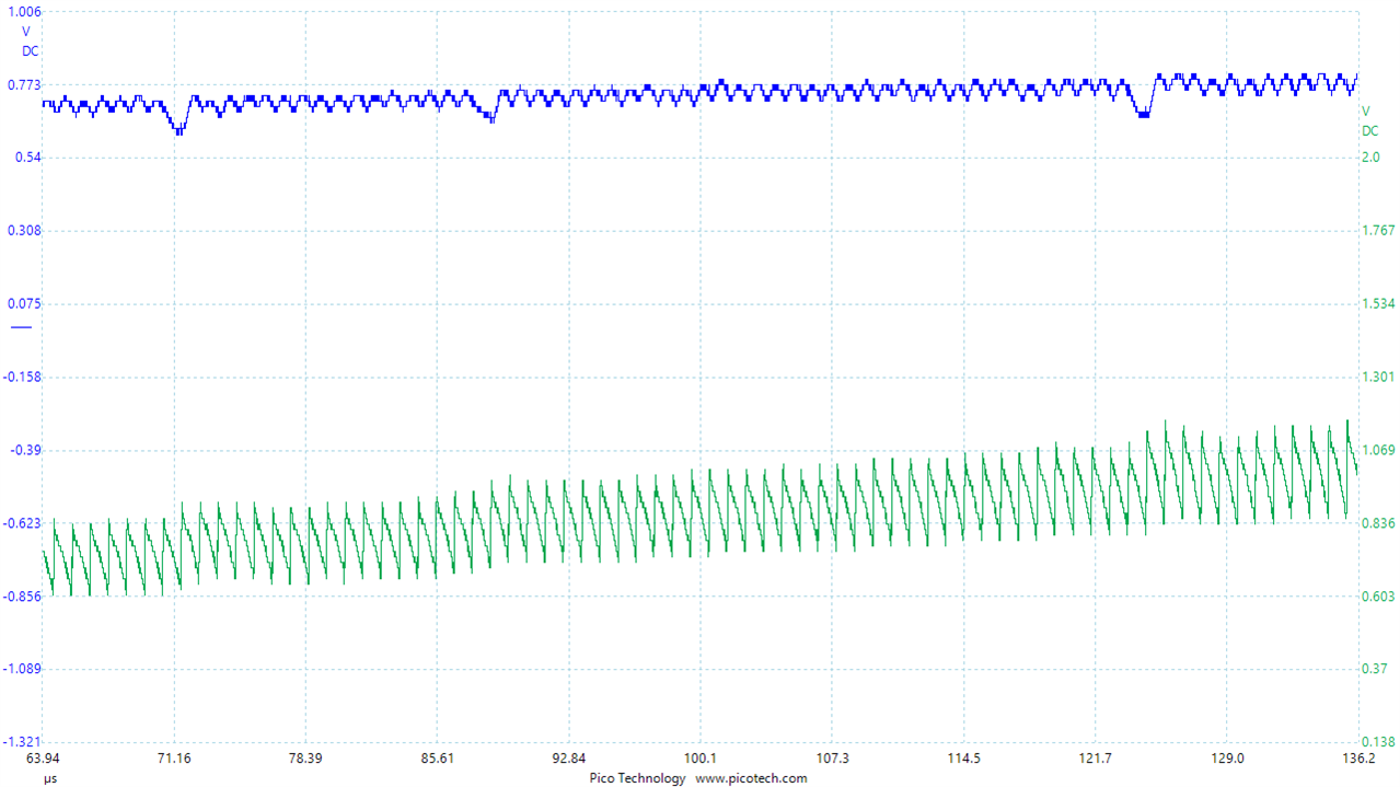
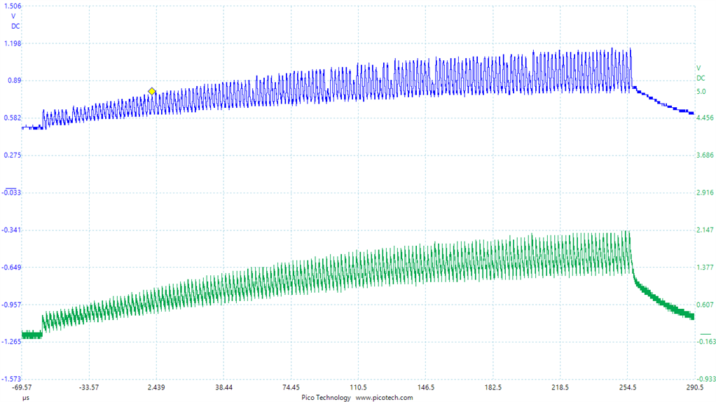
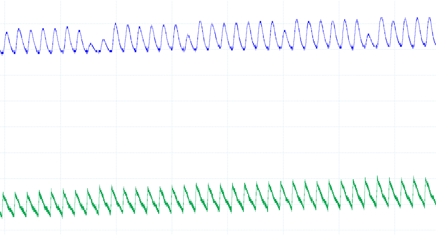
Sensed current waveforms on the output of the INA240 sporadically appear to be inverted, or significantly reduced in amplitude, compared with adjacent, correctly sensed, waveforms.
Blue: INA240A2 OUT
Green: Voltage measured across 0.1 Ohm resistive load, in series with 300 uOhm current sense resistor

Observe the undershoots in blue of INA output, that do not appear in true current waveform, visible in green.

(The load voltage (/current) increases following an INA output undershoot, as the compensator responds.)
Switch transitions appear to be "skipped" in the output of the INA240, or even a positive triangle inverted into a downward.
Application: high side current sensing for an average-current controlled buck converter.

Supply voltage: 5V from LDO. Decoupled with 2x 100 nF, 1x 1uF
Reference: 500 mV (ADR130AUJZ) decoupled with 100nF + 1 uF.
Half-bridge switching frequency is 1 MHz.
The switching frequency was reduced to 500 kHz, to exceed the INA240 BW by less margin.

Anomalies in output still observed, though now do not appear to be inverted, rather significantly attenuated.


The CM voltage that the IN+/- are exposed to is that represented by the green trace, load voltage.
No noise is observed on the supply or ground corresponding with the sporadic anomalies.
No CM or DIFF filtering has been added to the current sense input.
The target here is not to sense the peaks of the current waveform at the switching frequency, but rather the average current so the gain roll-off at 1 MHz was expected to be acceptable - but the anomalies effect the average.
Grateful for any guidance and advice. Issue has been observed on multiple IC units, and on INA240A3 and A2.


