- Ask a related questionWhat is a related question?A related question is a question created from another question. When the related question is created, it will be automatically linked to the original question.
Hello
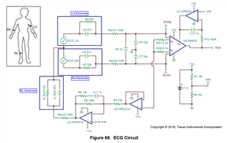
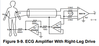
I am designing EMG amplifier with INA333 and OPA4376. I use 3 dry electrodes made of stainless steel. I saw many designs and read a lot, but after making a prototype it wasn't working. If there is anyone with experience with EMGs it would be very valuable if could answer some of my questions.
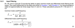
1. I couldn't get any signal from first stage of amplifier - after INA333. I tried Rg values from 300R to 4,7k Ohms. I saw 2 different designs than most. One with 47uF capacitor in place of Rg (no resistor) and another with 300Ohm + 22uF in series in Rg. I couldn't find any explanation to it in datasheets or any other designs. Do you know purpose of it? Is there any article explaining using a capacitor in place of Rg resistor or adding capacitor in series to Rg? Should I care more about input bias? Any equation for choosing capacitor and resistor for proper gain?
A: 47uF https://hackaday.io/project/8823-super-simple-muscle-emg-sensor
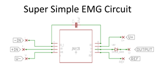
"The super simple EMG circuit uses a capacitors reactive impedance attached to the IA gain pins, which sets a variable frequency dependant gain, thereby only amplifying higher frequencies, and thus creating a similar affect to a high pass filter. The capacitors impedance (which is inversely proportional to the IA amplification) is calculated from below equation
Impedance = 1/(2 ∗ PI ∗ Frequncy ∗ Capactance)"
B: 300R + 22uF https://www.dfrobot.com/product-1661.html
When I tried 300R + 10uF it worked! But I don't know why and if it is correct way to design. There is not enough explanation around on the Internet and many designs just use a resistor in Rg (no idea if these designs were checked in real).
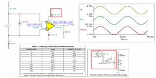
2. Is voltage divider with buffer a good solution to supply power to INA and OPA? I saw that I have like ~200kHz noise on Vref and it brings noise to signal output. Any solution to this noise? When I removed OPA and used only divider without buffer then noise was gone, but divider without buffer is generally not a good idea.
I know that opams don't like high capacitance on output, but does it apply to buffered divider? I have to use decoupling capacitors on INA and OPA supply so it will add capacitance to buffer. Seems like no one cares about output capacitance when using opamp as a buffer to get virtual ground. Can input capacitance (two 10uF) influence working of the buffer?
Maybe I should change to low noise negative voltage generator?