This thread has been locked.

If you have a related question, please click the "Ask a related question" button in the top right corner. The newly created question will be automatically linked to this question.

LM358: Why does the LM358 have different output frequencies for the same peripheral circuit?

Part Number: LM358


Hi Team,


This is Uni-Trend account FAE Kevin, nice e-meet with you. My customer is Chinese Top company in Multimeter and oscilloscope market. The customer has recently experienced some problems with the product functionality during the production of the multimeter, the following is a description of the problem. (2000 pcs samples are involved and the customer has the idea of returning them).


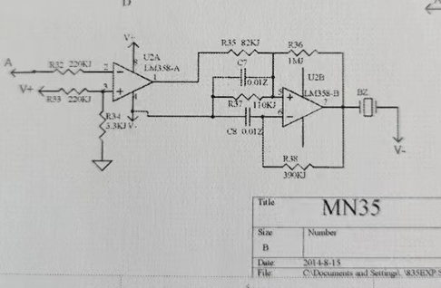
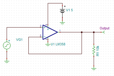
【Background】 The customer's multimeter products use the LM358P to produce square wave de-driving beeper. Below is the application circuit diagram for the customer's LM358P(The buzzer sounds when the 1-pin output is high). The customer reported that the beeper was not loud enough, and the loudness was normal after the LM358P was replaced, and that the same lot of sockets was at fault. The customer thought it was a problem with socket.

【[Problem phenomenon]】The sound of the beeper of a normal machine is significantly greater than the sound of an abnormal machine


【Problem Positioning】

  • 我们测量了正常机子LM358P输出电压的波形,输出频率是68kHz,最大值是8.56V,最小值是800mV;然后我们测量异常机子LM358P输出电压的波形,输出频率是5.05kHz,最大值是8.56V,最小值是800mV;
  • We measured the waveform of the output voltage of the normal machine LM358P, the output frequency is 3.68kHz, the maximum value is 8.56V, the minimum value is 800mV, and then we measured the waveform of the output voltage of the abnormal machine LM358P, the output frequency is 5.05kHz.8.56V max and 800mV min;


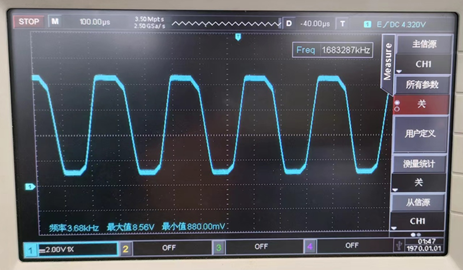
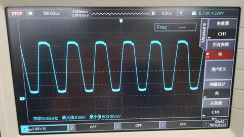
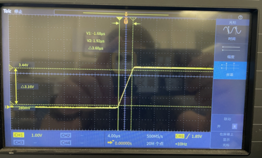
          Waveform of normal machine                                                               Waveform of abnormal machine

  • Find the data and learn that the beep is mainly in the 2k~4kHz range. We parallel the C8 of the abnormal machine with a capacitance of 2.2nF, where the output of the LM358P frequently changes to 3.6kHz and the buzzer sound reverts. This means that the abnormal sound is not caused by the operating and discharging output frequency.


【Question Point】

  1. 为什么相同的外围电路,运放的输出频率会不一样?
  2. Why do the LM358P output frequencies different of the same peripheral circuits?


【Guess】

  1. May be SR related. I have built a circuit to measure SR parameters for the LM358P, which is illustrated below.
  2. The SR parameter of normal machine LM358P is about 0.25V/us; the SR parameter of abnormal machine LM358P is about 0.87V/us; the two samples will have some differences in here.

                                           Abnormal machine

I have reviewed the specification for the SR parameter, there is only a typical value of 0.3V/us, and there is no mention of the maximum and minimum values, so do we have a range here? It seems that there is a difference between 0.8V/us and 0.3V/us. Is it in the range?


Problem Summary:

  1. Why does the LM358P have different output frequencies for the same peripheral circuit?
  2. SR typical for LM358P is 0.3V/us, are there maximum and minimum values?
  • Hey Kevin,

    Nice to e-meet you as well. It is not recommended to build a circuit with the slew rate as the limiting factor if you need a tight specification. There can be significant variance in slew rate across temperature and process.

    It is recommended to set your oscillation frequency with an RC constant. Below are a couple oscillating circuits, and the frequency is set by the passive components, and not limited by the slew rate of the op amps.

    https://www.ti.com/tool/CIRCUIT060042: Sine Wave Generator

    https://www.ti.com/tool/CIRCUIT060010: Triangle Wave Generator

    Best,
    Jerry

  • Hi Jerry,

    There may be some impact on the process, but is there some range for our SR parameters?
    Or is the SR parameter of 0.8V/us within the range of our device?

    The customer's application is already in mass production, so maybe we should discuss this circuit.
  • Hey Kevin,

    There is not a limit to the range of slew rate, otherwise it would be tested and listed in the datasheet. What is the quiescent current of the device?

    Best,
    Jerry

  • Hi Kevin,

    the buzzer itself can have an impact on the slew rate. Has the customer changed the buzzer model? Is it a piezo? A piezo shows a big capacitance which can have an impact on the OPAmp's slew rate. Eventually the insertion of an isolation resistor at the output of OPAmp could help. But without knowing your buzzer this is only a wild guess, of course...

    Kai

  • Hi Kai,

    The customer no change the buzzer, it just replace the LM358 and the function is recover.

  • Hi Jerry,

    Thanks. The quiescent  current we use the multimeter test and the AC current is 2.1mA, the DC current is 65uA.

  • Hey Kevin,

    The device is 500uA/ch typically, the DC current should not be 65uA. What pins are you measuring quiescent current on?

    Additionally, you may tell the customer that this is in the range of expected values for slew rate. I'm asking about quiescent current to confirm that this is just a higher bandwidth part that is at the upper range of the test limits, but still within specification.

    Best,
    Jerry