This thread has been locked.

If you have a related question, please click the "Ask a related question" button in the top right corner. The newly created question will be automatically linked to this question.

XTR117: Amplifiers forum

Part Number: XTR117

Hi,

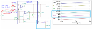
I´ve got this circuit mounted and it works well with XTR117.

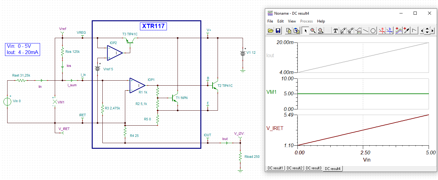
But I need to change my supply. In the picture power supply is 24V and i have 12V. When I change it, I don´t have the same values on current.

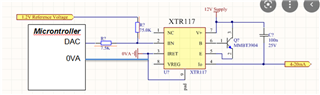
I found this circuit, but it doesn´t work.

What I´m doing wrong in the first picture?

What is wrong on the second?

Thanks on advance,

  • Hi Gonzalo,

    take care, the IRET pin is no signal ground but is freely floating relative to the 24V supply and its ground depending on the generated output current of XTR117. Because of this, you have to power the microcontroller with the VREG pin of XTR117. And if the microcontroller circuit consumes more than 3.8mA, then you have to change the design. Please read the datasheet of XTR117 very carefully to understand how it works.

    Kai

  • Hi Gonzalo, 

    Because of this, you have to power the microcontroller with the VREG pin of XTR117. And if the microcontroller circuit consumes more than 3.8mA, then you have to change the design.

    Please see Kai's comments. 

    XTR117 is 2-wire current loop transmitter. Iret node has to be floating and input signals including the MCU has to be referenced to the node, see the simulation below. 

    XTR117 0-5V 4-20mA 10262022.TSC

    XTR117 has a 5Vdc onboard regulator and it shall be used for supply the current (up to 3.8mA @5Vdc), and MCU's Ground shall be referenced to Iret node as well. The schematic's reference Ground is located at Vloop or V1 supply (12Vdc/24Vdc) side on the right of the image.  

    You noticed that Vref is simulated at 6.099Vdc (more than 5Vdc). If you measure between Vref and Iret nodes, you will measure at 5.0Vdc, which Iret node is floating.  

    As Kai pointed out, if CMU's operating current is greater than 3.8mA @5Vdc, you may have to use XTR111 or 3-wire current loop transmitter for the application. Alternatively, you have to find lower power MCU for the same 2-wire V-to-I transmitter application, if you want to use XTR117 part.

    You may be able to find additional current loop transmitter information in the link below. 

    https://e2e.ti.com/support/amplifiers-group/amplifiers/f/amplifiers-forum/945188/faq-designing-with-4-20ma-current-loop-transmitters-xtrs-faq-links

    If you have additional questions, please let us know. 

    Best,

    Raymond 

  • Hi Gonzalo,

    I have taken Raymond's simulation (thank you Raymond Relaxed) and added two important voltages, "VM1" and "V_IRET":

    "V_IRET" isn't constant but floats relative to the supply voltage of XTR117, depending on the input signal "Vin", while "VM1" remains constant. This indicates that the "IRET" pin of XTR117 is no simple signal ground !

    Kai