This thread has been locked.

If you have a related question, please click the "Ask a related question" button in the top right corner. The newly created question will be automatically linked to this question.

INA185: Output Cap oscillation

Part Number: INA185


Hi,

I'm using an INA185 as a voltage sensor.

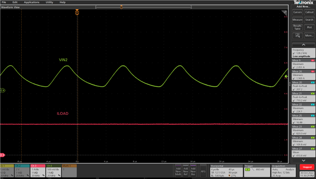
I put 0.1uF at the output side as a filter cap.

It will produce a  128k, pk to pk 700mV oscillation.

However, when I remove this 0.1 output cap, all the sensing signals go back to normal.

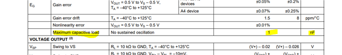
I wonder if there is any output cap driving ability for INA185?
Or is there any suggestion for output cap selection for INA185?

Thanks

  • Leo,

    Thanks for using E2E!

    This parameter can be found in section 6.5:

    100nF is 100x the recommended maximum load this device can withstand. If greater than 1nF is needed, I would recommend placing some amount of isolation resistance between the output node of the INA185 and the capacitor. Of course, this will introduce an RC time constant to the output on the other side of the capacitor. 

  • Hi,

    Thanks for your reply.

    I wonder what's the main reason that causes this oscillation?

    And why did TI suggest 1nF? Is there any risk that 1nF may also oscillate ?

    Does TI suggest adding 1nF for the output for filtering, or not? 

    Thanks

  • Leo,

    In general, capacitive loads erode phase margin for operational amplifiers. Normally, you can do a loop analysis to analyze the gain and phase margin of your respective system and how much impact a specific capacitive load will have on the op amp, but this becomes a bit more complicated when you start looking at current sense amplifiers. Here, the loop is completed internally to the device and you have no access to break it to perform this analysis. As a result, you can only look at closed loop characteristics to analyze stability, which is a bit more complicated. There are methods using closed loop output impedacne that can be followed to do this, but it is a bit complicated. We have some papers here detailing the method, and here showing a use case for ADC drive if you are interested.  

    To your question regarding the datasheet choice, designers will typically choose a value to a certain phase margin, but again, there isn't really a way for someone to validate this on a bench, so instead of phase margin, we specify this as a maximum capacitive load. 

    As to whether we recommend capacitance for output filtration, I would say that comes down to the specifics and needs of the system. Output filtration is nice for the removal HF content, but it comes with the tradeoff of reduced rise time, and of course the potential stability reduction I mention above. The INA185 should be able to drive the 1nF without issue. 

  • Hi Leo,

    TI is definitely not recommending to mount a 1nF cap directly from the output to signal ground. Just the opposite is true: The recommendation is to never intentionally mount a cap directly from the output of an OPAmp or current sense amplifier to signal ground because any capacitive load will minder the phase margin and decrease the stability, as already mentioned by Carolus. If you have to put a filter capacitance at the output for some reason, on the other hand, then always mount a suited isolation resistor between the output of INA185 and the filter capacitance so that a RC filter is formed. Then -and only then- even higher capacitive loads than 1nF can be used. See section 8.1.3. of datasheet. There is also a RC network recommended and not a single capacitor.

    TI has made a very nice training video series on stability and the effect of a capacitive load at the output of OPAmp, by the way. And allthough the INA185 is no normal OPAmp the videos are nevertheless very helpful to understand why a capacitive load can make issues:

    https://training.ti.com/node/1138805

    The datasheet specification of a maximum capacitive load of 1nF is valid for having the capacitive load directly mounted from the output to signal ground. It will withstand this mistreatment with "no sustained oscillation", as the datasheet says. This clearly means that increasing the capacitive load to more than 1nF, on the other hand, will result in sustained oscillation. Also, even if the INA185 may not oscillate with a capacitive load of up to 1nF, the speed performance will suffer and you will see an increased settling time, which is another good reason to not directly mount a capacitive load from the output to signal ground.

    The experienced circuit designer sees in this specification that the INA185 is a good-natured curent sense amplifier that will forgive even bigger stray capacitances at the output and that there's sufficient headroom for RC low pass filtering at the output.

    Kai