This thread has been locked.

If you have a related question, please click the "Ask a related question" button in the top right corner. The newly created question will be automatically linked to this question.

TLV8812: Eliminating noise

Part Number: TLV8812
Other Parts Discussed in Thread: REF3312, TLV2333

Hi Team,

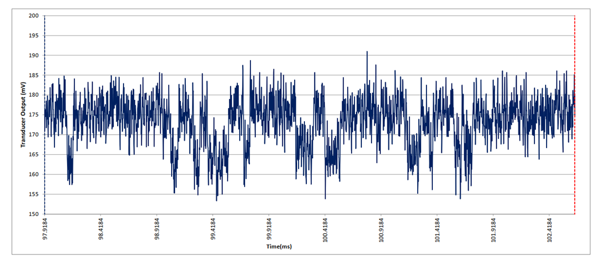
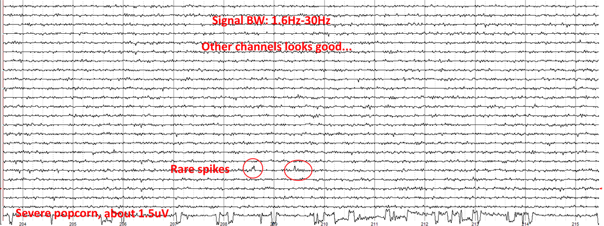
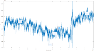
A customer is asking if there is a way to remove the noise they are measuring below:

Their application is a low-power device that needs measurement of current in the nano ampers resolution. The TLV8812 is used as a trans-impedance amplifier, with a feedback resistor of 909K ohm and a feedback capacitor is 1uF.

In the image above, they are measuring drifts, as a very slow wave, similar to a sine, in the frequency of 5mHz (milli Hz), with an amplitude of up to 300uV. This is measured with a fixed resistor and a fixed voltage (1.25V from ref3312) in the input.

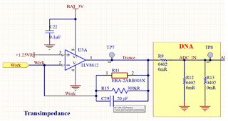
At the output, the final circuit is a low pass RC filter, with 150K ohm and 1uF

How do they eliminate this? 

Thank you in advance.

Regards,

Marvin

  • Hi Marvin,

    The TLV8812 is used as a trans-impedance amplifier, with a feedback resistor of 909K ohm and a feedback capacitor is 1uF.

    Hhm, the schematic is showing something totally different. Please show a correct schematic.

    And unfortunately the scope plot is not showing any time scale. So it cannot be said in what frequency range the noise appears. Please show a scope plot with time scale.

    The only remedy is to use low pass filtering with a corner frequency low enough to kill the spikes in the scope plot. 150k and 1µF gives a corner frequency of 1Hz which seems not to be low enough. In order to avoid too large capacitances, I would do some digital low pass filtering in the microcontroller, like moving average filtering or even some FIR filtering.

    Kai

  • Well visually it looks like popcorn noise. no one screens for that in a low cost part, perhaps the product groups knowns a better alternate. 

  • Hi Marvin,

    Is the TLV8812 noise test circuit inside a metal enclosure where the op amp is shielded from room air currents and extraneous electric fields, or is it on an exposed PC board?  If the circuit is inside an enclosure is the +3 V battery in there too?  When making long duration noise measurements in the lab I have found that unrelated electrical or physical events in the lab area can affect the noise measurement. Providing a proper noise measurement environment is required for accurate results.

    I agree with Michael that the big shift in the noise signature looks like a popcorn noise occurrence. However, the TLV8812 circuit is fabricated on a CMOS process and Popcorn noise is almost unheard of with CMOS op amps. Although I have observed it on some bipolar process based op amps, I have never seen it occur on a CMOS op amp.

    Kai mentions the absence of the O-scope time scale and that is needed. Additionally, it would be helpful to see if a longer time span shows more of the sudden noise shifts occurring.

    Regards, Thomas

    Precision Amplifier Applications Engineering

  • Hi Michael, hi Thomas,

    Although I have observed it on some bipolar process based op amps, I have never seen it occur on a CMOS op amp.

    If it actually is popcorn noise, it could be the popcorn noise of the REF3312...

    Kai

  • The pop shift of true popcorn noise is usually binary, as these nice examples show:

    Because of that I think that the customer is suffering from some additional noise sources or EMI.

    Kai 

  • Hi Kai,

    Nice images of popcorn noise examples. It will be interesting to see what additional information Marvin is able to provide about the TLV8812 noise test environment.

    Thanks for your helpful input as always.

    Regards, Thomas

    Precision Amplifiers Applications Engineering

  • Hi Thomas, and Kai,

    Thank you for looking into this. Please allow me until Monday to provide you with more information from the customer.

    Regards,

    Marvin

  • Hi Thomas,

    Thank you for waiting. The customer took time to respond due to a schematic update.

    Closing the device inside a metal enclosure is not an option.
    The device is battery-powered and tested by applying a constant voltage on a fixed resistor. as an input current to the trans-impedance amplifier

    They replaced the TLV8812 with TLV2333 in order to allow a higher gain of 3M, instead of 909K, and try a zero-drift amplifier. The TI amp has a reference voltage of 1.25V from REF3312, and added 4x2.2uF capacitors to the output of the REF3312. This reduced the amplitude slow drifts, which seem to be oscillations at 5mHz, I think it may be a stabilization issue.

    According to the latest findings, it could be that these small oscillations originate from the REF3312, and are amplified by the TI Amp gain.

    Can you confirm if this assumption sense? If so, can you suggest a more accurate series reference voltage with a low current?

    Regards,

    Marvin

  • Hi Marvin,

    I don't know of any voltage reference that has its noise performance specified down to the milli-Hertz range.

    But the simplest remedy here is to avoid the voltage reference all the way by running the OPAmp with a bipolar supply voltage and connecting the +input of OPAmp to signal ground Relaxed

    Kai