Other Parts Discussed in Thread: TINA-TI
Hi,
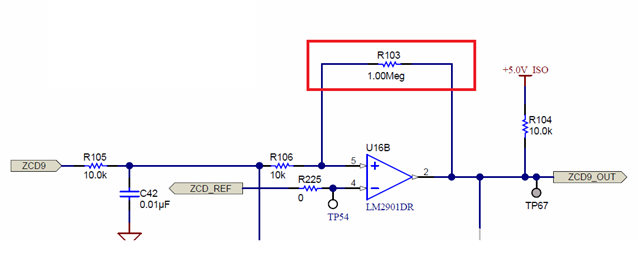
I need to understand why we place 1Meg resistor (R103) in below comparator circuit.
Also wants to understand the calculations for the same.

This thread has been locked.
If you have a related question, please click the "Ask a related question" button in the top right corner. The newly created question will be automatically linked to this question.
The positive feedback adds hysteresis. See, for example, Comparator with Hysteresis Reference Design.
Hi Jaydip,
adding hysteresis is a very clever method to make a comparator work very stably without adding unwanted extra output togglings when the input voltage is close to the threshold voltage. The feedback from the output of comparator to the +input (hysteresis) helps to traverse the threshold region of comparator faster and to a greater extent. Think about what it means to the +input of comparator when the output of comparator toggles from low to high or high to low with "R103" and without "R103".
The simplest method to find suited values for the components providing the hysteresis is to run a TINA-TI simulation. But don't forget to carefully read the datasheet first
Kai
Thank you Clemens and Kai!
Jaydip,
Thanks for reaching out. The positive feedback is what we call hysteresis. This allows you to eliminate unwanted transitions at the output, called "chatter", when you traverse through the thresholds with a slow-moving input signal. Here are some resources for you to learn more about hysteresis:
Inverting comparator with hysteresis circuit (Rev. A)
Non-inverting comparator with hysteresis circuit (Rev. A)
How to solve comparator noise problems with hysteresis - YouTube
-Chi
Thanks Chi for explanation.
While I was studying Non-inverting comparator with hysteresis circuit (Rev. A) page 3 step 6 the Vth is on inv terminal.
and I have taken Vth for calculation in Non-inv terminal in step 2 & 3. this consideration basis open virtual ground?
(inv and non-inv terminal potential are always same?)
how non-inv VTH will be same as the inv Vth? shown in figure?
For a comparator, there is no virtual ground; the two inputs are expected to have different voltages.
For a non-inverting comparator, the inverting input has a fixed reference voltage, and the non-inverting input has the input signal.
For an inverting comparator, the non-inverting input has a fixed reference voltage, and the inverting input has the input signal.
In both cases, the positive feedback goes to the non-inverting input; it does not matter which input gets shifted to get hysteresis.
I agree with you Clemens.
doubt is how Vth calculated in equation 6 basis on the Vth calculated on non-inv terminal?
Hi Jaydip,
There is no virtual ground in a comparator but equation 6 was based on that we want to create the threshold when you traverse through at the same threshold, which is why we also have VTH on the inverting terminal the same as non-inverting terminal. Technically you could have the VTH at the inverting input different to have asymmetrical hysteresis but here we wanted it at the midpoint. So thats why we have the thresholds the same for both calculations and pins.
Oh Ohk Understood well.
We took Vth equation equal to find R1 value in step 4..
How these two Vth can be equal (Step 2 Vth = step 3 Vth??)
In step 2, to get Vth we have taken Vh value and Step 3 to get Vth value, we have taken VL.
Many thanks in advance.
Hi Jaydip,
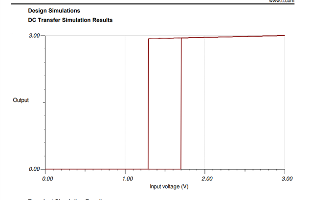
If you look at the hysteresis curve, when you traverse through the threshold transition region, you'll notice its sort of high and low at the same time in this transition which is why you can have the vth equal. Its only when you go beyond the VH or VL that the output has a defined logic level.
