This thread has been locked.

If you have a related question, please click the "Ask a related question" button in the top right corner. The newly created question will be automatically linked to this question.

OPA607: Evaluating whether the OPA607 can be used as a replacement for the OPA365.

Part Number: OPA607
Other Parts Discussed in Thread: OPA365,

Hi,

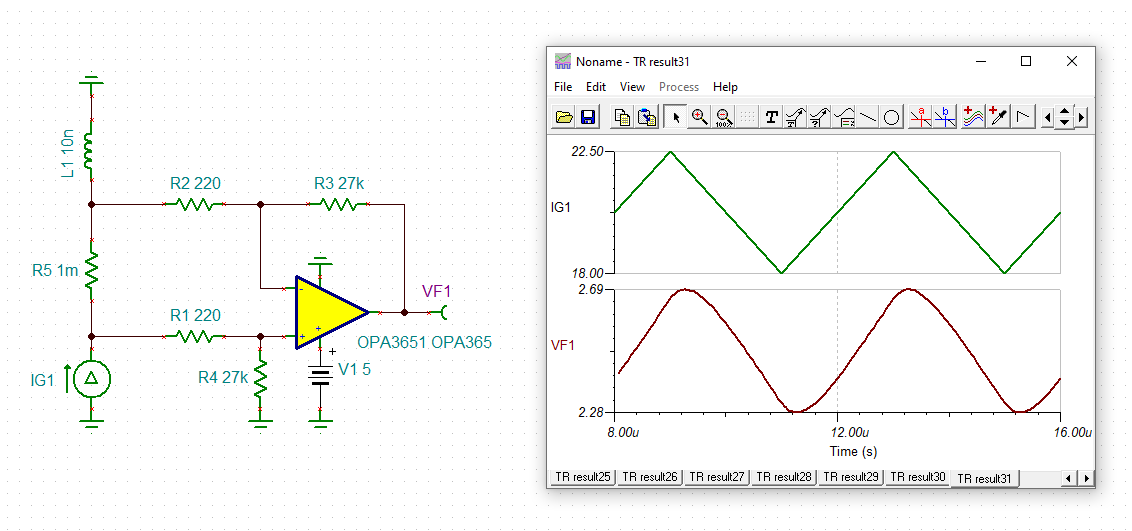
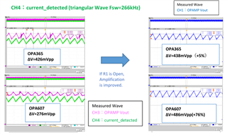
I am using OPA365 for current sensing.
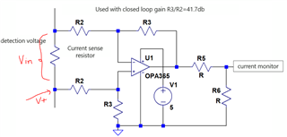
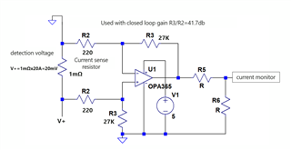
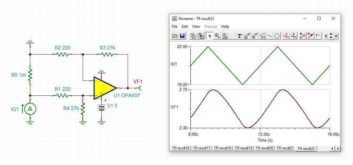
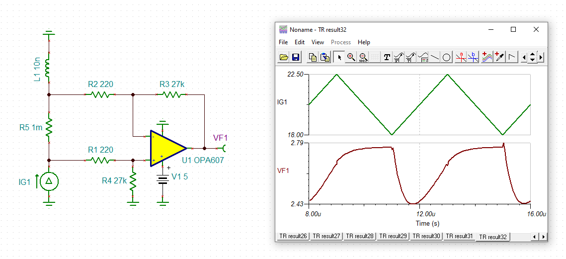
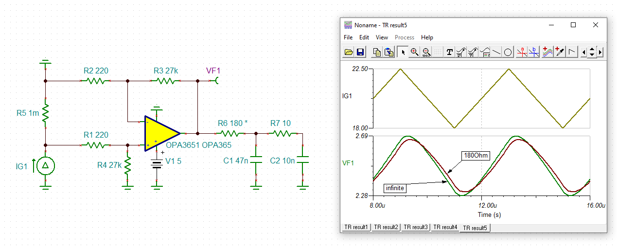
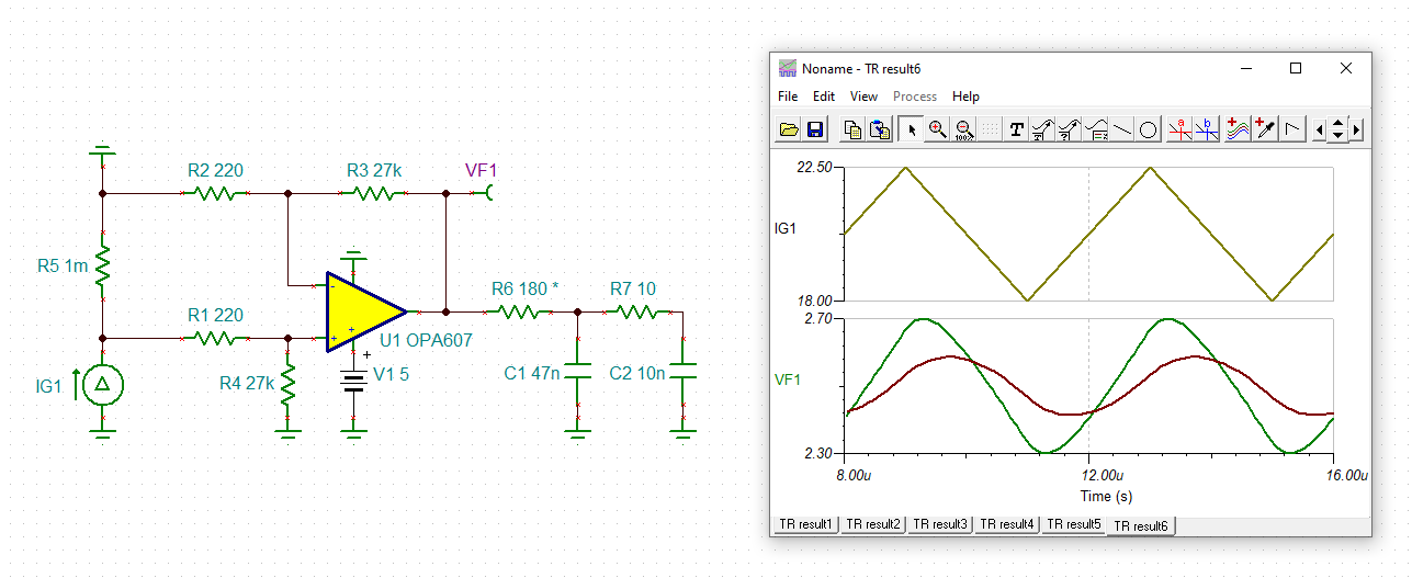
We are evaluating whether the OPA607 can be used as a replacement for the OPA365. Below is the circuit diagram.

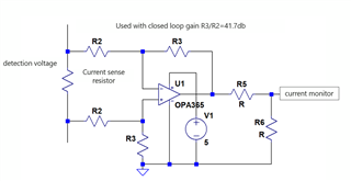
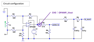
・The ratio of the resistance value of the feedback side and the input side is 41.7dB.
・The operational amplifier output is divided by R5 and R6 and used for current monitoring.


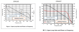
Question 1: Since the GBW of the OPA607 and OPA365 is 50MHz, is it correct to assume that the open loop gain and closed loop gain are the same?

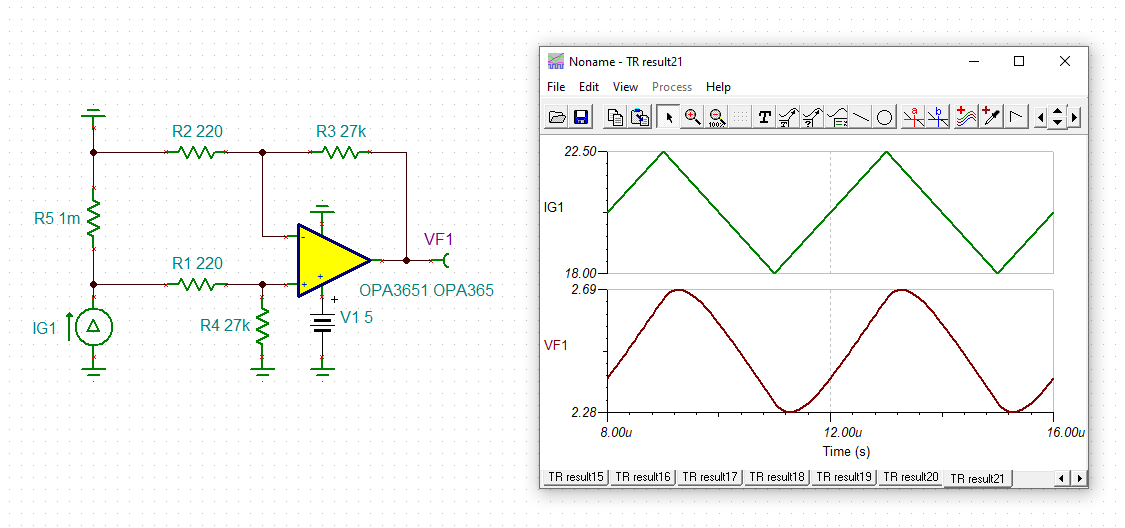
Question 2: What can be the reason for the approximately 35% difference in magnitude of the op-amp output waveform under the same conditions?

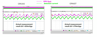
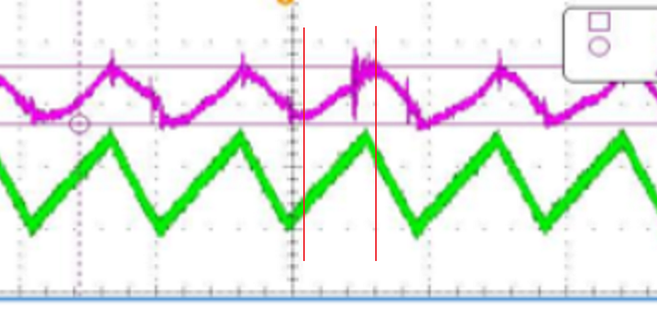
Question 3: What are the possible reasons why the waveform of the op amp output is distorted from the triangular wave?

Thanks,

Astro

  • Hi Astro,

    What's the value of R2 and R3 you have used in your circuit and how much is the V+ voltage (marked below in the image)? Also can you share the voltage (Vin) graph across the sense resistor?

    Regards

    Anant

  • Hi, Anant

    Register values are R2=200 and R3=27K.


    The waveform I sent you last time shows the current waveform of the output inductance. The voltage is detected by passing this current through the detection resistor. Therefore, the V+ voltage is the detection current IL times the detection resistance value 1mΩ.

    Thanks,

    Astro

  • Hi Astro,

    it should work:

    astro_opa365.TSC

    astro_opa607.TSC

    So something else is going on.

    Manufacturing tolerances of resistors could play a role. But I find the small needles and the periodically occuring ringing in the output signal in the scope plots more suspicious. Seems that the circuit is suffering from lots of common mode noise? Such common mode noise can develop when the shunt's ground is too far away from the signal ground of differential amplifier. Then even inductive ringing can develop which the OPA365 seems better to be able to suppress than the OPA607:

    Kai

  • Hi, Kai

    It is used in the following circuit configuration.
    ・When comparing the output waveforms of OPA365 and OPA607, a difference occurred. ΔV of OPA607 is about 50% of OPA365.
    ・OPA365 and OPA607 have almost the same waveform when R1 is opened.

    Question:
    ・It is thought that ΔV became small because the OPA607 was connected to a circuit with low output impedance. Are there any problems with this usage? I am concerned about exceeding the component rating.
    ・If there is no problem, I would like to use this method, but will ΔV change with temperature and time?
    I am concerned that the change will be large compared to the high impedance circuit connection.
    ・Please explain in detail the mechanism by which the amplitude of the OPA607 becomes smaller. It is easy to understand if there is a comparison of the internal circuit with OPA365.

    Thanks,

    Astro

  • Hi, Kai

    Would it be possible for you to answer the three questions I posted earlier?

    --------------------

    Question:
    ・It is thought that ΔV became small because the OPA607 was connected to a circuit with low output impedance. Are there any problems with this usage? I am concerned about exceeding the component rating.
    ・If there is no problem, I would like to use this method, but will ΔV change with temperature and time?
    I am concerned that the change will be large compared to the high impedance circuit connection.
    ・Please explain in detail the mechanism by which the amplitude of the OPA607 becomes smaller. It is easy to understand if there is a comparison of the internal circuit with OPA365.

    --------------------

    Thanks,

    Astro

  • Hi Astro,

    as the simulations show, the OPA607 cannot handle the heavy load (180R, 47nF, 10R and 10nF) as well as the OPA365.

    The OPA365 draws a supply current of 4.6mA while the OPA607 draws only 0.9mA. This is a huge difference. Also, the OPA365 shows an open loop output impedance of 30R compared to 500R of the OPA607. This is also a huge difference. All this indicates that the OPA365 has a way more robust output stage compared to the OPA607 and can much better hanlde your heavy load.

    You can see from the simulations that the OPA607 is driven far beyond its abilities. You can try to increase the 180R and 10R resistances and decrease the 47nF and 10nF capacitances and by this weaken the load.

    Kai

  • Hi, Kai

    Since changing the circuit constants (180R, 47nF, 10R, 10nF) requires evaluation man-hours, we would like to use it as it is if we find that there is no problem in operation. Please let me know if there is any information such as ΔV changes with temperature or over time when used with a heavy load compared to a light load, or that the rating of the operational amplifier is exceeded.

    Also, in the simulation, the peak of the purple waveform lags in phase from the peak of the current waveform, but in the measured waveform there is no phase lag. Why is the phase delayed?

    Thanks,

    Astro

  • Hi Astro,

    I begin to repeat myself: The OPA365 consumes a much higher supply current compared to the OPA607 and because of this has a way stronger output stage. Distortion of OPA365 is specified down to a 600R load, see figure 13 of datasheet. Distortion of OPA607, on the other hand, is only specified down to a 2k load, see figure 7-9 of datasheet. This also indicates that the OPA365 has a stronger output stage.

    Now consider that a 47nF cap presents an impedance of 14R at 250kHz, which is even lower at the harmonics of signal. So, you "short circuit" the output of OPAmp with an impedance of about 180R. And the OPA365 with its way stronger output stage can way better handle this short-circuit than the OPA607.

    Kai

  • Hi, Kai

    I was able to understand from your answer that there is a performance difference between the output stages of the OPA365 and OPA607.

    Q1) If the OPA607 is used under these conditions, will there be any problems with its operation?

    Q2) In the simulation below, the peak of the red waveform lags behind the peak of the current waveform. Why is the phase delayed?

    Thanks,

    Astro

  • Hi Astro,

    you cannot use the OPA607 in this circuit, unless you redesign the output filter into a higher impedant version. The output filter you use right now short circuits the output of OPA607 at 250kHz and its harmonics.

    When you carefully look at the scope plot then you will see that there's a phase shift as well:

    Also keep in mind that the simulated circuit is highly simplified and does not contaiin all the parasitic inductances and stray capacitances of the real circuit. And there's additional noise coming from the input (HF ringing) which is not modelled in the simulation either. But the simulation is good enough to find out that the OPA607 is no good choice here.

    Kai

  • Hi, Kai

    I understand that the OPA607 should not be used.
    Looking at the scope plot you sent, it is indeed phase-shifted. Can you tell me the possible factors as the reason for the phase shift? It will be easier to understand if you explain the internal circuit as an example.

    Thanks,

    Astro

  • Hi Astro,

    the phase shift is caused by the finite open loop output impedance of OPAmp. An ideal amplifier would have a zero Ohm output impedance. But real OPAmps differ from that. The OPA365 with its strong output stage and higher supply current provides an open loop output impedance of 30R while the OPA607 with its weaker output stage and much lower supply current shows 500R. This is a huge difference and explains why the OPA365 works properly here and the OPA607 not.

    Kai