Because of the holidays, TI E2E™ design support forum responses will be delayed from Dec. 25 through Jan. 2. Thank you for your patience.

This thread has been locked.

If you have a related question, please click the "Ask a related question" button in the top right corner. The newly created question will be automatically linked to this question.

LM675: Distortion/noise only when load is connected.

Part Number: LM675
Other Parts Discussed in Thread: LM1875

Hi, I have the circuit below. 1 inverting amp and 1 non inverting:
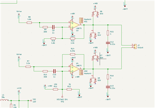
The circuit works fine when no load (or large R loads) are connected. However, when I connect a 16 ohm high power resistor the signal distorts as shown in the video:

Any suggestions?

  • Hello Ismail,

    I have a couple of questions about your LM675 circuit:

    1. What is the -BATT voltage level?
    2. What are the characteristics of input signal, frequency, voltage, waveform type, etc.? It's difficult to make them out in the video.
    3. Similarly, what are the expected output signal characteristics?

    From the video the distortion occurring when the 16-Ohm load is added at the output looks like it may be high frequency oscillation modulating the intended output signal. Try the same load test with the input at some mid-range, or other dc level, with and without the 16-Ohm load. See if you obtain the distortion waveform for that condition.

    If high frequency oscillation is occurring, the circuit may not be correctly compensated. How did you determine the series RC network shown connected between each LM675 inputs?

    Regards, Thomas

    Precision Amplifiers Applications Engineering

  • Hi Ismail, 

    Adding to Thom's comments. LM675 is a decompensated op amp which is intended for gains on 10V/V or higher configuration, please see the link below. 

    https://e2e.ti.com/support/amplifiers-group/amplifiers-internal/f/amplifiers-internal-forum/186539/lm675-spice-model-or-equivalent?tisearch=e2e-sitesearch&keymatch=LM675%2525252525252520simulation#

    I also noticed that when output signal is distorted with 16Ω load, both input signals are also distorted. It is difficult to see the output voltage amplitude from the video, please send us the screen shot and/or describe the output swing and frequency. 

    I also heard the humming sounds when the load is engaged. Can you tell us where the humming noise is generated from? Can the 48Vdc source the 16Ω load load or similar without significant changes in %load_regulation. 

    Best,

    Raymond

  • Hi Thomas,

    1. -BATT is at 0V, it is coming from a PSU

    2. I have a wien bridge oscillator going through a buffer, feeding the opamps input. 20V, 700 Hz, sinusoid

    3. I expect an output of 40 V at 700Hz, gain of 2, per op amp. I need an 80Vp-p differential output

    It looks like the noise is 330 kHz, which is the switching frequency of my 48V supply.

    As for the RC network, I took it from the data sheet of the LM675 (page 9). I actually didnt see a difference with it being on or not on the PCB, so I took the  components off.

  • Hi Raymond,

    The link you provided does not work for me. I added some info in my response to Thomas.

    The yellow and blue waveforms you see in the video are the outputs of each op amp, the red is just the oscilloscope's math function taking the difference.

    correct, when the load is connected, there is some buzzing. I am not sure where it is coming from, I think it is coming from the op amps - not the 48V supply. the 48V supply is 350W.

  • Hi Ismail,

    Thank you for all the information. I suspect the the key point is that the noise is very possibly power supply ripple passing through to the LM675 output, and not an oscillation. The LM675 has little power supply rejection ratio (PSRR) remaining at 330 kHz and in which case any noise at the V+, or V- pins will couple directly through the op amp to its output. Datasheet Figure 7 shows the PSRR vs Frequency performance of the LM675, but only out to 20 kHz so we don't know exactly how low the PSRR becomes at 330 kHz.

    More heavily loading the LM675 output with the 16-Ohm resistor demands more current from the power supply. Likely, the power supply ripple is increasing with increased current demand from the LM675 driving the load. Your schematic doesn't show the power supply bypass capacitors that are being used at the +48 V supply powering the LM675. There needs to be an effective bypass capacitor having very low impedance at 330 kHz connected from the LM675 V+ pin to ground. If it isn't an effective bypass, the ripple has a free pass to the LM675 output!

    Do let us know what you are using as the power supply bypass capacitor at the LM675 V+ pin.

    Regards, Thomas

    Precision Amplifiers Applications Engineering

  • Hi Thomas,

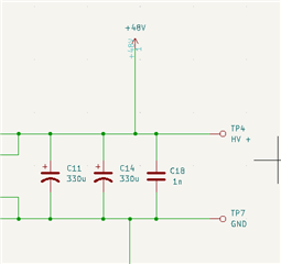
    See below:

  • Hi Ismail,

    The 1 nF has too high of capacitive reactance at 330 kHz to be effective, and the 330 uF capacitors likely have too much self-inductance (ESL) to be effective at that frequency as well. Try a capacitor of about 47 nF or 100 nF, right from the LM675 V+ pin to ground. See if that helps reduce the supply noise coupling through to the LM675 output.

    Regards, Thomas

    Precision Amplifiers Applications Engineering

  • Hi Ismail, 

    I do not know why you are unable to access the previous link. Anyway, I cut and past the last two replies from the link, where it talked about the minimum gains for the decompensated op amp. 

    the 48V supply is 350W.

    Thom has addressed in this part. Please make sure that 48Vdc's ripple voltage is low and 48Vdc supply is well decoupled. Please apply 16Ω load directly to the 48Vdc supply rail, and monitor the %Load regulation, changes of the ripple voltage amplitude and current. If the 48Vdc is low ripple and stable voltage source, LM675's output should behave in a similar manner (it does not look like an oscillation and LM675's PSRR vs. frequency is a bit poor.). 

    From the video, it looks that the noisy output follows the input signals with gains. 

    Best,

    Raymond 

  • Hi Ismail,

    I think it's fully normal that the scope shows noise when you touch the scope probe with your hands. This will even make the stablest circuit appear to be instable. Your body works like a receiving antenna for all sorts of EMI in your ambient and by touching the circuit (scope probe) you directly inject this EMI into the circuit (scope probe).

    I would think about building up the circuit with a more modern OPAmp for which a Spice model exists. Perhaps the LM1875 or one of these:

    https://www.ti.com/de-de/amplifier-circuit/op-amps/power/products.html

    Kai