This thread has been locked.

If you have a related question, please click the "Ask a related question" button in the top right corner. The newly created question will be automatically linked to this question.

GRAS 47AC PreAmp Circuit

Other Parts Discussed in Thread: PGA2505, PCM4204, JFE150, JFE2140, JFE2140EVM, OPA1671, OPA1678, INA163

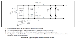
I'm designing a preamplifier for a GRAS 47AC microphone. It is a Pre-polarized 1/2" CCP mic with a frequency range from .09 to 20kHz. Does anyone have recommendations for a pre-amp and ADC combination? I've been looking into the PGA2505 and PCM4204, but any advice would be welcome.

  • Hi Michael,

    any low noise requirement?

    Kai

  • Kai,

    If you're referring to the frequency range I'd like to keep it above .4Hz minimum. As far as interference I'd like to keep noise as low as possible. This mic is an unbalanced output, which is throwing me off a bit because almost all of the chips are balanced input. 

    Mike

  • Hello Michael, 

    There are a lot of great options to choose from. The PGA2505 is a great option if you need to control the gain programmatically. Other options include using a discreet JFET such as the JFE150 or JFE2140 paired with a bipolar op-amp for ultra low noise and a high impedance front end as outlined here:

    https://www.ti.com/lit/an/slpa018/slpa018.pdf?ts=1669073560917&ref_url=https%253A%252F%252Fwww.ti.com%252Fproduct%252FJFE150

    I just completed the JFE2140EVM and the users guide shows a similar circuit as the app note above. There are trade offs between the two I can assist with.  

    https://www.ti.com/lit/ug/slpu010/slpu010.pdf?ts=1669073808221&ref_url=https%253A%252F%252Fwww.ti.com%252Ftool%252FJFE2140EVM

    Other great options are the OPA1671 and OPA1678. We provide some application circuits in the product datasheets below. 

    https://www.ti.com/lit/ds/symlink/opa1671.pdf?ts=1669073504008&ref_url=https%253A%252F%252Fwww.google.com%252F

    https://www.ti.com/lit/ds/symlink/opa1678.pdf?ts=1669074001017&ref_url=https%253A%252F%252Fwww.google.com%252F

    Let me know if you have any questions I can help with on these devices. 

    Best Regards, 

    Chris Featherstone

  • Thank you for your help. Is the preamp shown as an example capable of handling the mic's phantom power, or does it need a circuit like the one in the PGA2505 datasheet? If this circuit is needed I assume it would go between the mic cable and the node connecting to the 10k resistor and 10u capacitor.


  • Hi Michael,

    in some publications the "GRAS 47AC" is operated with the "NI 9250". I recommend to download its datasheet to see how your microphone should be connected and powered.

    I think the microphone contains a simple JFET circuit to provide an impedance conversion. The internal circuit is powered by a constant current source. "CCP" means "constant current power". The "NI 9250" drives a constant current of 2mA into the microphone circuit up to an compliance voltage of 19V. Because the microphone expects a constant current power, the datasheet does not say anything about the DC output voltage of microphone when being properly biased. This makes it a bit difficult to bias the microphone by the help of a resistor (which is the simplest form of constant current source Relaxed). When powering the microphone with 18V DC, a 9k resistor would limit the current into the microphone to < 2mA. It depends on your output signal amplitude whether a simple resistor biasing will properly work. If you want amplitudes of several Vpeak, it may be the better choice to operate the microphone with a true constant current source instead of a simple resistor.

    Having a JFET impedance converter internally of microphone seems to mean that the output of microphone is single-ended and not differential.

    By the way, the noise of "NI 9250" is about 50nV/SQRT(Hz) at 1kHz. This is not super low noise. So it should not be all too difficult to build an amplifier showing noise in the same range.

    Nevertheless, it can be a good idea to use a pure JFET or MOSFET amplifier (at least in the first stage) in order to avoid issues with "popcorning" noise, BJT circuits can sometimes suffer from. See Chris's link.

    Kai

  • Hello Michael, 

    Considering the low frequency requirement I might suggest looking first at the circuit for the JFE2140EVM. You can see below the transfer function has a gain of 1000V/V or 60dB down to very low frequencies (Even much further down that what I measured). This can be accomplished with the JFE150 as well however will require a very large capacitor. The tradeoff is slightly better noise performance with the JFE150. Below I have attached an application note on phantom power as well. Please let me know if I can help further with your design! I can help with the understanding of the EVM circuits as well. 

    JFE2140EVM Gain vs Frequency:

    https://www.ti.com/lit/an/sboa320a/sboa320a.pdf?ts=1669150127111&ref_url=https%253A%252F%252Fwww.google.com%252F

    Best Regards, 

    Chris Featherstone

  • These answers have helped me understand how the preamp stage of the circuit works. I think I can use one of the OPA1678 or INA163 chips for this part. Are there any special considerations I need to know when applying phantom power to a single ended audio input? Normally it's connected in parallel between the V+ and V- lines, do I do the same if I have V+ and GND?

  • Hi Michael,

    I would do it this way:

    michael_opa1678.TSC

    The GRAS 47AC is driven by a quasi constant current source. R8 should be optimized for 2mA. Because the supply voltage noise gets immediately injected into the signal path, a capacitance multiplier arround T1 is used for the noise filtering. R1 and C1 provide a corner frequency of low pass filtering of 0.07Hz. The current gain of T1 allows a much higher filter resistance then when omitting T1: Only about 1/100 of the 2mA load current is flowing through R1 which keeps the voltage drop across R1 very low.

    R11 helps to discharge all capacitances during power-off. D4 prevents discharging currents in reverse direction through T1. C8 enhances the stability of capacitance multiplier and R12 limits the inrush current through D4.

    C6 and R9 provide the necessary AC coupling of signal and provide a high pass corner frequency of 0.07Hz.

    C6 may store enough energy to destroy the OPAmp input in certain situations. Because of that R3, D1, D2 and R2 provide a protection circuit for the OPAmp. D1 and D2 clamp over- and undervoltages to the supply rails while R3 limits the current through these diodes to safe level. 18V across R3 results in 18mA and a voltage drop across D1 or D2 of less than 1V. R2 limits the current to 1mA then. This scheme with two resistors and external clamping diode has the advantage that the resistors can be kept low, allowing a very low noise level. With one current limiting resistor allone the resistor would need to be 18k, which would add a lot more of noise.

    Because I do not know what gain you need in the first stage I have choosen a gain of about 21V/V. Take care, R6 plays an important role referring to noise. Because only a small value in the kOhm range will work here, any capacitor in series to R6 to provide a high pass filtering would be huge (in the 1000µF range!), if a bandwidth down to 0.09Hz is wished. Because of this a cap is omitted here. Instead, a high pass filter removing any offset voltages is added to the output of circuit.

    The 100µF caps should be aluminium electrolytic. Mount a X7R ceramic cap of 100...470nF in parallel to each of these caps.

    R3 and C4 provide an additional signal low pass filtering. A must for a 16MHz OPAmp when the input signal comes from an external source. C5 also provides some low pass filtering and guarantees a good phase margin. By the way, professional circuits do always contain this sort of passive bandwidth limiting at every single OPAmp stage.

    Kai

  • Hello Michael, 

    Let us know if you have any further questions. Great explanation Kai! 

    Best Regards, 

    Chris Featherstone

  • Thank you for your help. I hadn't realized I need so many current limiting circuits to keep the Op-Amp safe.