This thread has been locked.

If you have a related question, please click the "Ask a related question" button in the top right corner. The newly created question will be automatically linked to this question.

LMH6624: LMH6624MAX NOPB amplifier noise reduction when used to measure the current with shunt.

Part Number: LMH6624
Other Parts Discussed in Thread: LMH6629, LMH6609, OPA855

I am using this IC for voltage amplification for measuring current with shunt value of 0.03E. 

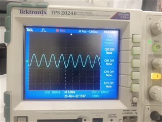
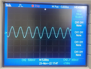
What I am seeing here is, 800mV sine wave with time 5ns. [measurement scale of 500mV and 5.00ns with MSO]. Even when I short the inputs.

What could be a reason.

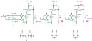
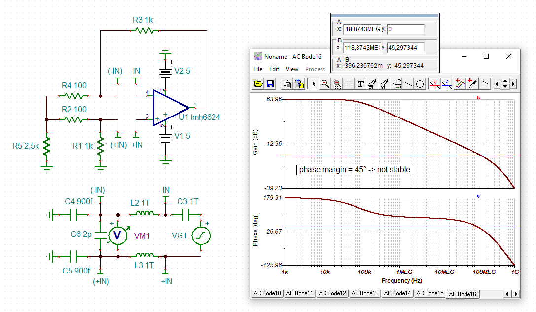
I need amplifier band width of 1GHz. In circuit there are 5 stages of amplifier with each gain of G1 = 5, G2 = 5, G3 = 5, G4 = 1, G5 = 1. 

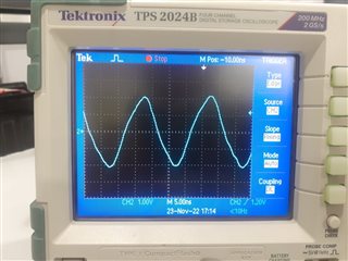
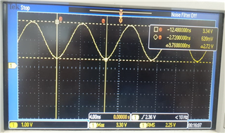
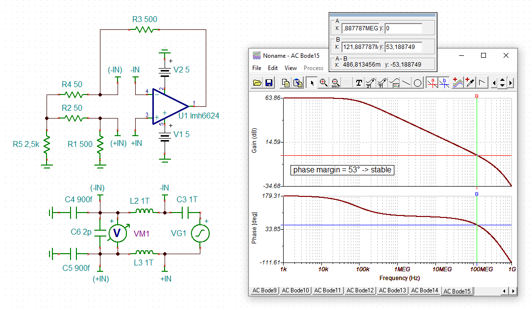
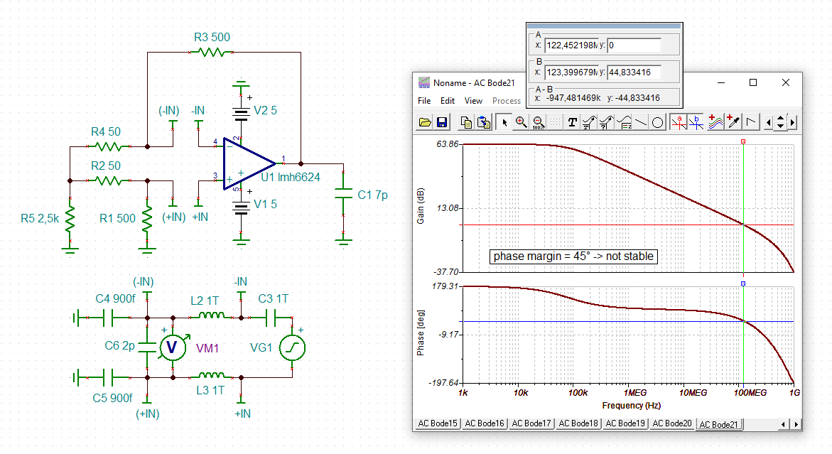
when Rf = 5k and R1 = 1k changed to 500E and 100E respectively. This noise reduced from 2V pk-pk to 800mV pk-pk.

Please see attached waveform for both. 

Target is to reduce it to minimum to measure current of 100mA. 

  • Hi Anurag,

    your circuit is oscillating. Keep in mind that the LMH6624 is a decompensated OPAmp and needs a minimum gain of 10V/V to operate stably. Please look into the datasheet.

    Kai

  • Hi Kai,

    Thanks for your reply. 

    I understand your point. Then how can I use bandwidth of 1GHz if I keep gain of >= 10.

    I have to measure the harmonics up to 500MHz. 

    Is there way out.

  • Hi Anurag,

    the gain bandwidth (GBWP) is 1.5GHz, but not the bandwidth. As an example: 100MHz bandwidth at a gain of 10V/V gives a gain bandwidth of 1GHz but still a bandwidth of 100MHz.

    Kai

  • Hi Kai,

    Yes. Understand.

    Then if we reduce the gain below 10, cannot be used for more bandwidth and with keeping oscillation very small?

    What is our requirement is, we need amplifier with 1GHz bandwidth. Can you please suggest if this does not work. 

    Thanks,

    Anurag

  • Hi Anurag,

    the LMH6624 is no good choice. Also, if you want to accurately measure harmonics up to 500MHz, then you should choose an OPAmp with a bandwidth of >1GHz to have enough linearizing gain reserve.

    Kai

  • Thanks Kai. Can you please suggest some good part numbers matching with our requirement. 

  • Hi Kai,

    Please see the gain settings

    W (mW) Input Current (A) R (Shunt) V (Input Voltage) G1 G2 G3 G(total) Vout
    0.003 0.01 0.03 0.0003 -10 11 11 -1210 -0.363
    0.3 0.1 0.03 0.003 -10 11 11 -1210 -3.63

    Still, it is showing the noise of around 102.45MHz sine wave. 

    ~85mA current is flowing through shunt. Shunt value is 0.03E

    please see schematic.

    Thanks, Anurag

  • Hello Anurag,

      Is this with the LMH6609 or the LMH6624? The LMH6609 in this case is not decompensated, but is lower bandwidth compared to LMH6629. 

      The above table looks to be the expected design requirements. Is the measured scope with input or both inputs of the amplifier to ground (is this the meaning of noise?)

    Thank you,
    Sima 

  • Hi Sima,

    LMH6624MAX NOPB is used. Application is simple to measure the current (< +-100mA) with all harmonics up to 100MHz. 

    When I short the inputs, I get the waveforms as 

    so I tried to make each amplifier gain equal and more than 10.

    but not resolved. 

    Please have look at schematic. 

    Thanks, Anurag

  • Hello Anurag,

      The schematic looks fine in terms of avoiding oscillations for the LMH6624 since it has been adjusted with the higher gain. Can you share a snippet of the layout?

      I would also suggest probing with the scope at the first stage after R12 that is populated with a small value resistor. 

    Thank you,

    Sima 

  • Hi Anurag,

    I think the feedback resistance is a bit too high:

    anurag_lmh6624.TSC

    Ok, the difference in the phase margin is not very big, but can spell the difference between success and failure. See the gain peaking in figure 46 when you choose a higher feedback resistance than 500R.

    And see what happens, when you add even the least amount of stray capacitance to the output of OPAmp:

    So please increase R12, R13 and R14 to 100R again, as already mentioned by Sima. Have these isolation resistors connected closest to the output pins of OPAmps.

    Decompensated 1.8GHz (GBWP) HF-OPAmps cannot be treated like slow standard OPAmps. They are high breeded racehorses and don't forgive even the smallest mistake.

    Kai

  • To answer your question of how to get this set of gains to give over 1GHz closed loop BW, you should perhaps switch to the much newer OPA855,