This thread has been locked.

If you have a related question, please click the "Ask a related question" button in the top right corner. The newly created question will be automatically linked to this question.

LM311-N: DIFFERENCES IN PINOUTS FROM STANDARD CADENCE ALLEGRO DESIGN AND PSPICE FOR TI

Part Number: LM311-N


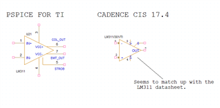
Have been using Capture CIS 17.4 for a few months now and have been using components from the Cadence standard library. I've just started using Pspice for TI and I gather looking at other threads that trying to simulate a circuit in PSPICE for TI, created using Capture CIS 17.4 won't work very well as I've found this out. Thats ok, I can re-do the circuit but I've noticed that for instance the LM311-N comparator in Pspice for TI has pin assignments that don't match up with the datasheet unlike the standard Capture CIS 17.4. Can anyone explain this? Is it something to be concerned about? further down the line when I start generating a PCB file?

  • James

    thanks for your post. I see what you’re referring to. Does appear to be an error in PIN numbers. We’re on holiday break until Monday and we’ll address at that time. Sorry for the delay. 
    Chuck

  • Hi James,

    Thank you for reaching out. It looks like the pspice for ti has the right pinouts to me but wrong pin numbers. I wouldnt rely on pin numbers in the pspice tool and would rely on datasheet pin numbers. However we will look into this and make the changes. 

  • Hi James,

    Thanks again for your patience. I am not quite sure where you got the model on the right but the pspice for ti and the one thats current on the web is the one to use. But yes, the PIN numbers are incorrect (pin out names are correct however) so we will be making a revision on this. 

     slcm011a.zip

  • Hi Chi, Thanks for that. The model on the right was from the component library in Cadence CIS 17.4.