This thread has been locked.

If you have a related question, please click the "Ask a related question" button in the top right corner. The newly created question will be automatically linked to this question.

INA281EVM: INA281EVM DC Measurement issue

Part Number: INA281EVM
Other Parts Discussed in Thread: INA281, INA241B, INA296B

Dear Community,

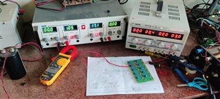
I had bought a INA281EVM board recently for testing of the INA281B4 IC for my application. However I have encountered the following problems:

1. The DC measurements are not linear. 

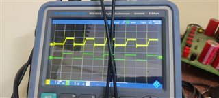
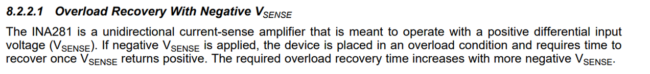
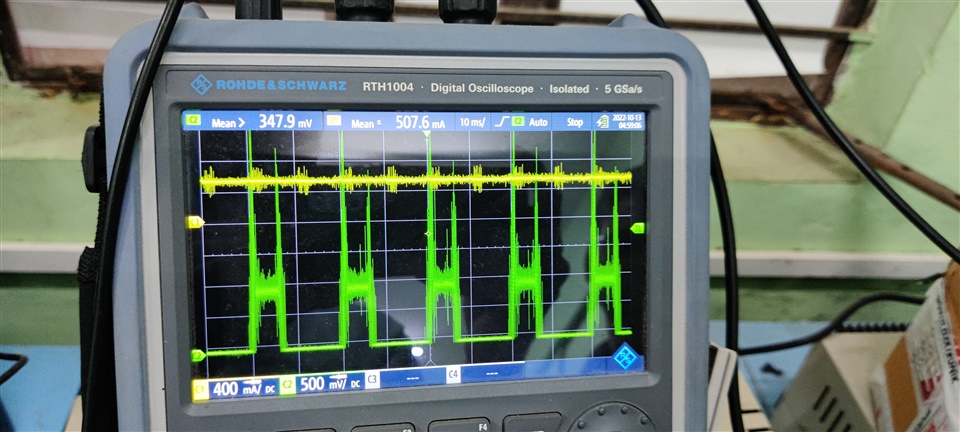
2. The DC current measurements give a pulsed output of some specific frequency with a lot of noise. I am not able to debug the issue.(image attached)

Thanks,

Ashwin K

  • Hi Ashwin,

    it's impossible to help with so little information. Please give way more details.

    What do we see in the scope plots? Can you scope the voltage drop across the shunt? Are you really measuring a DC current?

    Kai

  • Hello Ashwin,

    I agree with Kai.  Some more information is desired to get a better understanding of the issue.  From looking at this scopeshot with limited information you n could be having an overshoot condition from a negative voltage to positive voltage which will cause issues as there is an overload recovery time.  This is stated in the datasheet.  Could you also explain the expected result vs the scope shot above.

  • Hi Kai.

    Yes. I am measuring a DC Current. I have generated the DC current using a current source and that is the yellow waveform that I have scoped using a current probe. The green plot is the output of the EVM board across the output pin and GRND.

    Ashwin 

  • Hi Javier,

    The expected result must be a DC measurement but the one I am getting is a sort of pulsed response (green) with a lot of noise.

    Ashwin 

  • Hi Ashwin,

    but the yellow curve doesn't look like a true DC current. It's contaminated by HF-noise all over. The INA281 tries to amplify the superimposed HF-noise as much as it can because it thinks that it belongs to the signal and because of this the output signal of INA281 is also looking noisy.

    Kai

  • Hello Ashwin,

    Can you share more details.  Is there some switching voltage or current that you want converted to DC?  Also I can you share your DC current expected, Rshunt and expected DC output voltage?  I can calculate the last one.  The DC output of the INA281 should be DC as well like your current probe.  The more information you can share the quicker we may get to the root cause of the issue. Can you share a schematic of what you are connecting to the EVM.  What is your VCM?  

  •    

    This is my test setup. For a DC Current of 1.05A, I am getting a drop of 10mV across the sense resistor as the sense resistance is 10mohm(as given in the datasheet). I am using a gain of 200V/V so I should get a output voltage of around 2V but I am getting almost zero across the output using a multimeter.

    Thank you,
    Ashwin K

  • Hello Ashwin,

    Please connect the VCM of your current to a voltage that is reference to the GND of the INA281.  The setup at the moment has the inputs connected to a supply that is most likely floating and this could violate ABS Max.  If you either connect the GND of the INA281 to the GND/Lowside of your current source or connect a voltage source between the two that does not violate ABS max you should be good.  Because ABS max could have been violated I am not sure if that INA281 has survived and this depends on parasitics and high much ABS Max was violated. So you may have to try the other pinout version if that is the case.

  • Hi Ashwin,

    I see two issues, the floating signal ground as already mentioned by Javier and the way you generate the 1A measuring current. Usually, a lab voltage source has an adjustable output voltage and an adjustable current limit. But you have not set an output voltage but only a current limit. This can cause the lab voltage source emit a noisy measuring current.

    I would recommend to set an output voltage different from zero and to limit the current by the help of a resistor as shown below:

    ashwin_ina281.TSC

    Of course, you can choose any other output voltage and any other current setting resistor resulting in a different measuring current. In the example above the 10R resistor limits the current from the lab voltage source to about 1A and causes the same current to flow across the 10mR shunt. This gives a voltage drop across the shunt of 10mV which is amplified by the INA281 by a factor of 200V/V resulting in an output voltage of INA281 of about 2V.

    And take care that all involved grounds are properly connected as shown above.

    Kai

  • Hello Kai,

    The DC measurement issue was resolved. The issue was with the floating ground measurement.

    However, when I used it to measure a 100kHz pulse with 50% duty ratio I didnt get the desired results. There was problem with the rising edge of the waveform. Can you please help ?. The green waveform is the current that is voltage that is sensed and the yellow waveform is the output of the IC.

  • Hello Ashwin,

    I believe this could be a situation where the voltage at the Rshunt is slightly negative causing a slight overload recovery inside the device.  I have showed a snip from the datasheet that discusses this issue.  You could place an offset on the device on purpose with a resistor in series the issue with doing that is you will add an offset and a gain error that you would need to calibrate.  Another alternative is to use the INA241B or the INA296B which are devices that is just released that is bidirectional.  Below is an example of adding a resistor to give you an offset.  It is using the IB of the device to create the offset.  If the voltage is switching at the inputs of the INA281 I would recommend using the INA241B as well just to mitigate the issue with VCM switching. 

    Here is an example of adding a resistor and it changing the offset.  This would need to be calibrated per device as the IB will vary from device to device.