This thread has been locked.

If you have a related question, please click the "Ask a related question" button in the top right corner. The newly created question will be automatically linked to this question.

OPA1622EVM: EVM Releases Magic Smoke

Part Number: OPA1622EVM
Other Parts Discussed in Thread: OPA1622, , OPA1637EVM

Testing an opa1622evm and powered it with 2x 13v batteries. I then connected the balanced output of a topping e70 dac to it and with no load the evm measured 4.8 vrms in and at the output of the evm. So far so good. The chip wasn’t heating up, voltage was stable, and dc was a few millivolts at the output. I shut it down, and lowered the the output to -4db in the dac and connected a  cosmos adc to it in mono mode at 4.5v input level( 800 ohms input impedance). I turned the evm back on then the dac and poof. Magic smoke. Dac and cosmos adc are fine.  The opa1622 blew near C5. I don’t see what adding the 800 ohm load from the cosmos adc would have done to cause this. On the output of the evm which is SE, I connected only pin 2 and 3 of the xlr cable going into the balanced input of the cosmos adc( ground or pin 1 was not connected). The cosmos adc and the dac were connected to my laptop which was operating on battery. The dac was also connected to 110v. Does anyone have any ideas? Thx for any thoughts.

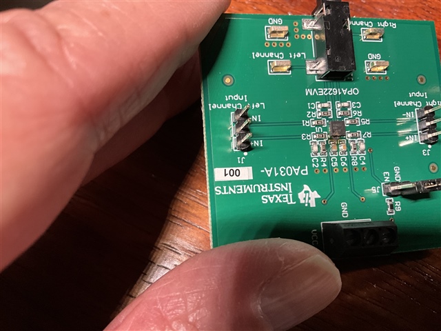
  • Wanted to add this

  • Hi,

    looks like a massive overvoltage event. Have you measured the applied DC voltages?

    Kai

  • I used to batteries each putting out 13.2v. It was fine until I repowered it with the adc connected.

  • Hello, 

    C5 is the decoupling capacitor for VCC. In your setup, is it possible that the VCC of the OPA1622 shorted to the 110V line somehow? The other possibility is that the input could have seen a short to the 110V and the input protection diode was forward biased and created a path during the short. This does appear to be an overvoltage event. Is it possible to know what DC voltage the input would have seen during this event? 

    Best Regards, 

    Chris Featherstone

  • Hello, 

    To follow up, another possibility is if the output of the OPA1622 was exposed to an over voltage event. The output protection diode could have been forward biased in the same way that the input could have been. Is it possible that this node was temporarily exposed to high voltage?

    Best Regards, 

    Chris Featherstone

  • The topping e70 dac had at most 5mv dc at it’s output. The dac is in a case and it was the only thing connected to 110. I had just taken the evm out of its packaging so no chance of exposure to over voltage. It did work perfectly  before I attached the outputs of the evm to pins 2 and 3 of the balanced input to the  cosmos adc which was connected to the battery powered laptop via usb. The ground pin 1 of the xlr cable going into the adc was not connected to the evm.

  • Could it have anything to do with the 3 prong 110 ground on the dac vs the floating ground between the two 13v batteries which of course was connected to the ground at power in block of the evm?

    Both the dac and the cosmos adc were connected via usb to the battery powered laptop.

  • Hello, 

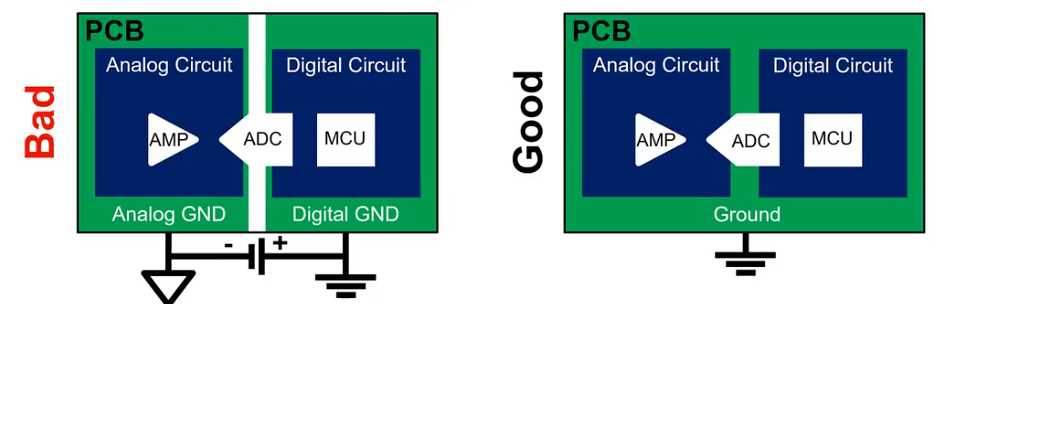
    I believe what you are experiencing is a voltage potential difference between the EVM ground and the ground connections on the DAC and ADC. Similar to the image below from our TIPL series (link below), a voltage difference may appear when there is not a common ground connection. By ground I mean a potential of 0V or mid-supply.  

    https://training.ti.com/mixed-signals-grounding-and-bypass-capacitors

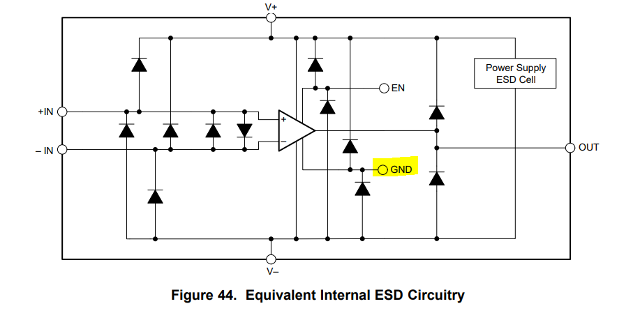
    The OPA1622 has a ground connection that is tied to ESD diodes to the supply rails. If the GND on the EVM is lifted beyond the rail in a fault condition, damage such as this may occur. It is difficult to say the exact root cause during the event, however best practice would be to have a common return current path (GND of 0V potential) available between the mixed signal components in the system. 

    Are you able to share how the batteries are powering the EVM? Can you illustrate the battery connection and how it forms a split supply to the EVM?

    Best Regards, 

    Chris Featherstone

  • Thx Chris. The battery setup is simple. There are two 13v lithium batteries in series. Positive on one battery to + on evm. Negative on the 2nd battery connected to - on evm. Where the 2 batteries are connected together in series, a connection goes to gnd on the evm.

  • Hi C Gib, 

    Thanks, that sounds pretty straight forward. I believe the issue is with the ground connection. Let me know if you have any other questions. 

    Best Regards, 

    Chris Featherstone

  • So what exactly would you recommend I do in this particular case re grounding? The only other thing I can see doing is connecting pin 1 on the xlr cable balanced input to the cosmos adc to the GND on the SE output of the evm.

  • Hi C Gib, 

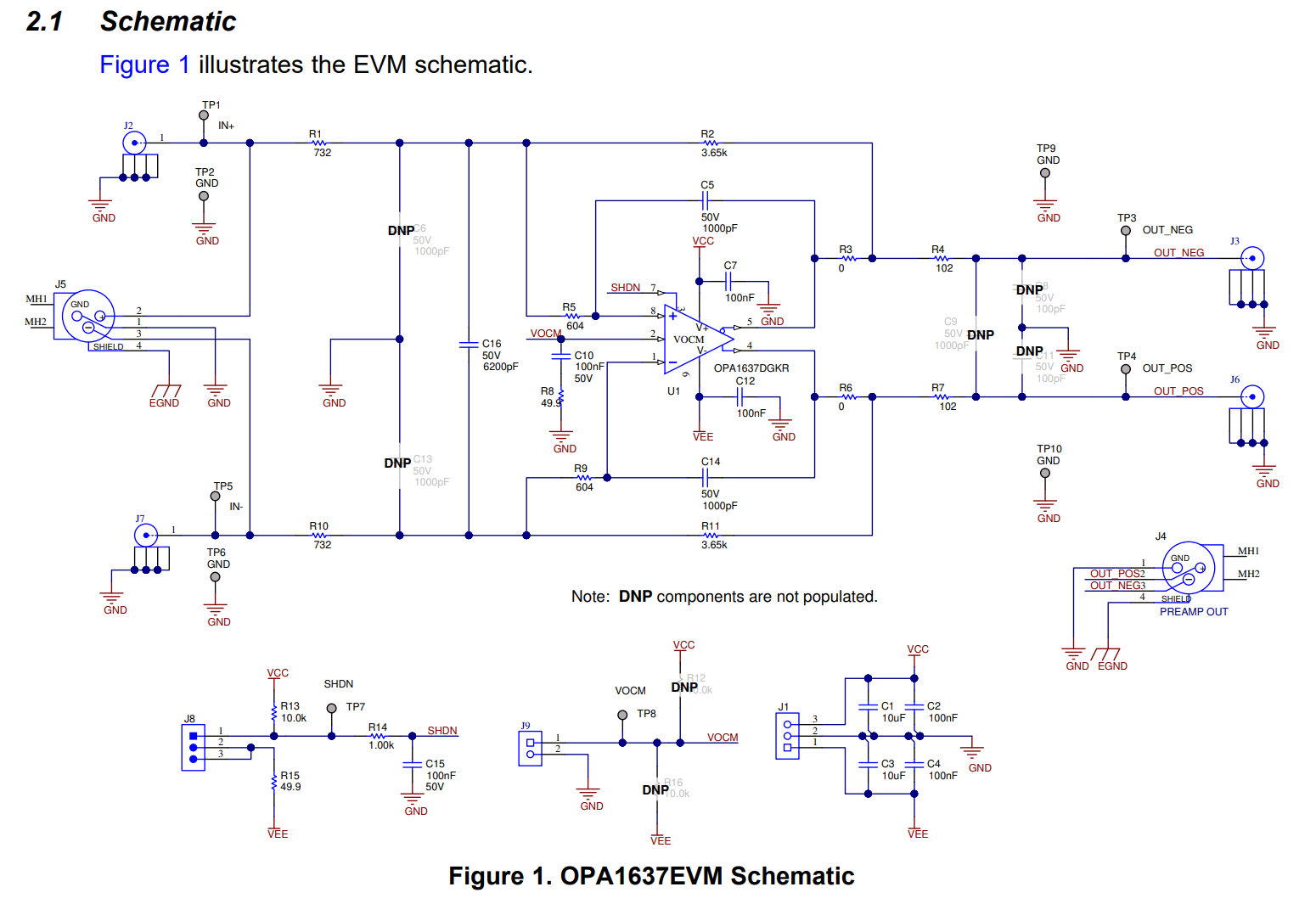
    The xlr ground should be tied to the evm ground on both the input and output. As an example of an evm that has xlr connections, I have attached the OPA1637EVM schematic below for reference. Since the output is single ended, the connection going into the ADC would be similar to the BNC connections below on the output. Specifically J3 or J6. One signal pin either 2 or 3 of the xlr can be tied to the EVM output while pin 1 ground would be tied to the EVM ground. There is no shield EGND to connect on the EVM. Please ensure that no high voltage is present on the board prior to handling. 

    Best Regards, 

    Chris Featherstone

  • Thx again Chris. One more question if you”ll indulge me. Let’s suppose pin 1 of xlr to the adc is connected to gnd on the evm and pin 2 is connected to output on the evm. That leaves pin 3 floating and there will be noise consequences  at the adc input, right? Measuring things at -120 db thd+n is tricky to begin with. Won’t this really muddy the water?

  • Hello C Gib, 

    Yes you are correct. Differential signaling provides the best noise rejection and improved THD by reduction of even order harmonics in comparison to single ended setups. Below is a little bit of information on the benefits of fully differential amplifiers. Let me know if you have any further questions. 

    https://e2e.ti.com/blogs_/b/analogwire/posts/precision-fully-differential-amplifiers

    Best Regards, 

    Chris Featherstone

  • So in this case would you recommend grounding pin 3 along with pin 1?

  • Hi C Gib, 

    The XLR that is used for feeding the ADC could actually be setup such that pin 2 is connected to one of the EVM outputs, either right or left and pin 3 could be connected to the other output. Pin 1 would be connected to ground. 

    Best Regards, 

    Chris Featherstone

  • I did understand that from your differential reference above, but if I was just to use 1 channel of the evm, would you recommend re xlr into adc, pin1 to  gnd of evm, pin 3 to gnd of evm, and pin 2 to + signal out of evm?

  • Hi,

    I've been reading through this and thought I would just quickly reset; here's how I understand it: 

    You have a DAC that has a balanced XLR output.  You want to connect this to the OPA1622 EVM, then, connected back in to your ADC.  For the DAC output, there are the two balanced lines and ground.  The OPA1622 EVM is really intended to take a L and R channel differentially (as in, 4 total lines, a L channel with +/-, and a R channel with +/-) and convert each separate channel to a single-ended output that can drive a standard headphone (L/R/ shared GND).

    You are taking each of the differential lines from the DAC, and putting the positive on one channel, and the negative on the other.  So, your L and R will be basically inverted copies of each other.  There is no L/R channel, just one channel, both amps on the OPA1622 will have the same (but inverted) signal.  Note that GND will be common for both channels, so the GND pin needs to serve as the GND for the OPA1622 EVM, as well as the GND for the negative inputs on each of the channels.

    Then you are taking the output from each amp. and going back into an ADC - so one amp's output will be the positive input for the ADC, and the other will be the negative, and the ground should connect all the way through; the GND should be connected on both the EVM and to the XLR pin 3, and also should be the negative inputs for the OPA1622.

    Agreed if you only want to use the ADC in single-ended mode, then you would use GND on both pin 1 and pin 3.  But, isn't the ADC a differential-input ADC?

    Regards,
    Mike

  • Sorry, now I see the confusion. I am taking only 1 balanced channel from the dac, inputing that into 1 channel on the evm, then taking the se output of the evm into the balanced input of the adc.

  • Ok, when you say "balanced" - to me that means differential, meaning it has to be two differential signals (+/-) and a ground.  If you only take one of the outputs of a "balanced" signal, by my definition it makes it "unbalanced".  But I think I see what you are saying, you only want one of the outputs of the DAC, going into a single amp, and then taking that amp's output and feeding to the ADC.  

    Is there a reason why you want to only use one side of the DAC's differential signal?  The OPA1622 will convert a differential signal to single-ended.

    Regards,
    Mike

  • Thx Mike. This was a test as I am going to feed the se output of the evm into a device that is se input but wanted to test the amount of harmonic distortion and noise that was introduced by the evm. So eventually 2 differential  signals into the evm (l and r) and will take the 2 se outputs from the evm into 2 se channels of another device. I ordered a few more evm’s which should arrive shortly and will take a fresh look. Just didn't want to blow any more up!

  • Ok, let us know when the next round comes in how it goes.  I'm calling this "Resolved" for now but you can open this thread back up when you get more results.

    Best Regards,
    Mike