This thread has been locked.

If you have a related question, please click the "Ask a related question" button in the top right corner. The newly created question will be automatically linked to this question.

OP Selection/Reference Design for Multiphase Current Measurement

Other Parts Discussed in Thread: INA250, LM7322

Hi expert,

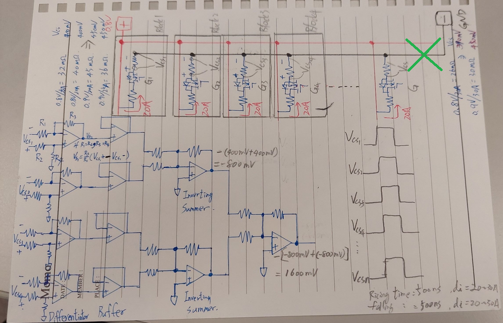
Customer would like to design a 20 loops current measurement. 

The test current pattern as below:

1. amplitude: 25A  ( On time : 200us / Off time :800us)

2. rise/fall time: 500ns/500ns

3. current converts to voltage e.g. 25A >> 0.4V

4. the 20 loops need to be synchronized and summed up, 0.4V*20=8V(max) 

Their original thought is to implement with OP as an adder and find a way to measure and observe the waveform in the scope.  Below is a draft block diagram. 

The challenge they think about is the rise and fall time need to be synchronized without time delay. 

Would you please suggest what kind of OP would be suitable for this kind of application? Do we have a reference design like this? 

Please share with us your valuable experience by any chance. It would be nice if the design could be done by purely HW without SW involved.  

Regards,

Allan 

  • Hi Allan,

    Here is a reference design using INA250 to accomplish a somewhat similar mission, although it deals with essentially just two loops (to borrow the term from you). The underlying principle is similar to the adder circuit you attached. 

    Regarding the selection of specific devices, you’ll probably want some with decent slew rate and step response. The first stage is not too bad, but the summing amplifier needs to be at least 16V/S in order to minimize delay. But I believe we have OP that can satisfy such requirement.

    Regards, Guang

  • Hi Allen,

    measuring across 20 shunts seems to be highly laborious. I would try to carry out the measurement here:

    And, with a bit luck, you even don't need to insert a shunt, if the line shows enough resistance at this place.

    Kai

  • Hello 

    I am  the owner of this requirement.

    When this circuit is used to measure different products, the current capacity, layout, positive & negative polarity position and size of the lead-out terminals are different. We cannot design a current load with a capacity of 300~500A  on a main board, so we must use 25A/piece is more in line with the actual situation, and the method is more flexible.

    Perhaps, I will change the design of its 25A/piece to 100A/piece to reduce the complexity of the design.


    +/-15V or +/-12V power supply
    Range 1
    On time/Off time: 200us / 800us
    Min F : 1Khz
    Range 2
    MOn time /Off time : 20us /80us
    Max F : 10kHz
    Rising time : 0.5 V/us
    Falling time : 0.5 V/us

    F : 1~10kHz
    Vout : about 20V (+/-10V)
    SR= 2*pi*f * Vout = 1.256 V/us

    Non-inverting amplification
    R1 : 1k
    R2: 9k
    Noise Gain : 10

    inverting amplification
    R1 : 1k
    R2: 1k
    Noise Gain : 1

    Estimated selection of material Unity Gain Bandwidth
    Unity Gain Bandwidth : 20Mhz
    Bandwidth : Unity Gain Bandwidth /  Noise Gain = 20Mhz/10 = 2Mhz

    0.35 = TR * BW
    TR(rise time) = 0.35/ BW = 0.35/ 2Mhz = 0.175us

    I found a LM7322 for this design, is it suitable?
    https://www.ti.com/product/LM7322

  • Hi,

    While dynamic performance is certainly important, now is also a good time for a rough estimate of DC accuracy to see if system requirement is satisfied. For example, some of the main factors to consider include offset and gain error.

    LM7322 sure looks promising, but I’ll ask colleagues specializing in this and related products to provide additional comments.   

    Regards, Guang

  • Allan, Kao,

    The buffers are not needed and the summers can take any number of inputs. 

    Don't let the op amp output voltage reach VOL (or VOH) because the "overload recovery" delay will slow responses time. Using a dual supply voltage or connecting R4's and summer IN+ to a reference voltage will keep all the amplifiers in the linear output voltage range. I suggest a small reference voltage, like 200mV; smaller voltages will introduce less error from common mode rejection due to resistor matching. 

  • Hi Kao,

    differential amplifiers built with discrete resistors usually suffer from low common mode rejection due to resistor imbalances caused by manufacturing tolerances and uneven temperature and long term drifts. Have you already determined the amount of common mode noise the circuit has to suppress? Do you have scope plots of the signal across the shunts and the common mode signal at the low ends of shunts referring to signal ground?

    Kai