Part Number: OPA828
Other Parts Discussed in Thread: THP210, THS4561
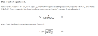
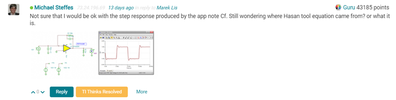
So I still have not seen a reply on the one question I had in this thread, what equation for Cf is Hasan using in his Zt excel designer.
I was looking at SBOA354 again, and it kind of repeats an old (somewhat misleading) rule of thumb on LG closure rate not being 40dB and the transimpedance feedback pole must be below the noise gain zero intersection with the GBP curve - that is a more like a caution, not a requirement as I had tried to describe at the end of this article,
So, just to illustrate this again, lets use that recent 4th order butterworth requirement from this thread and design the first stage as a peaking transimpedance stage with a lower Q 2nd order 2nd stage FDA MFB filter as per this thread,
So if we are targeting a particular Fo and Q in the OPA828 Zt stage, that requires a specific feedback R,
And before we get too far, make sure the input C's are in the model, here is the 1st test adapting the Aol test circuit, This give a Ccm + Cdiff of 10uF/668kHz = 15pF
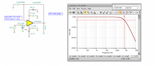
Then changin to just a unity gain follower to isolate on te Ccm, this gives 10uF/1.13MHz = 8.8pF. The data sheet says, 9pF Ccm and 6pF Cdiff. so that 15pF total is exactly right in the model - good job.
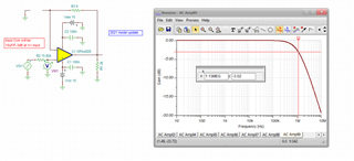
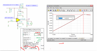
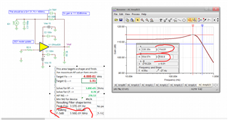
Now going into a 4th order Butterworth design, the 4kHz Fo from that other thread is too low, shift it all up to 400kHz, So here I am still using a 100pF source Cand it solves for a 389kohm gain with a 0.78pF feedback cap. This pole is happening above the NG crossover at about 400kHhz with an actual noise gain pole at 525khz or 5.25/4 = 1.31X over the crossover = actually the target Q here,

Changing the OPA828 sim to this case, and yes there you go, the expected 3dB peaking and 554kHz F-3dB. So this is obviously working even though it violates what SBOA354 says. Now of course the closure rate is actually a little below 40dB/dec but what is really going on the feedback pole starts to pull the phase shift around the loop up off of -180deg a decade before the actual pole.
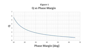
I could run the LG sim for phase margin, but this plot from that same 1st article tells me at a Q=1.31, I have about 42deg phase margin, there will of course be some variability here as teh GBP changes, and if I was recommending this kind of thing for production I would definitely steer folks towards a supply current trimmed device - not sure the OPA828 is trimmed actually.
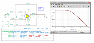
And then to continue to a 4th order 400kHz Butterworth, use that 2nd stage FDA but back to the THS4561 designed for Fo=400kHz and Q = 0.54. The THP210 will be too slow, Went to a gain of 5 in this stage, kind of pushing the available BWin the THS4561, but give it a try.
And here is the 2nd stage showing the correct response and no apparently instability, It is important here to try and hold an input Z around 2kohm to keep the OPA828 GBP close to 45Mhz,
Now lets put this after the Zt stage to get an overall 4th order 400khz Butterworth, little off on the response, but not much, not 400kHz F-3dB but instead about 468kHz with a little bit of peaking, not sure why, but it basically works and demonstrates using a Zt stage with a feedback pole above the LG=0dB crossover. I wonder if maybe (with <1 loop gain around Fo) the open loop output impedance of the OPA828 is adding to that series input R to the filter. That might be a good reason not to do this, but still showing ok results.
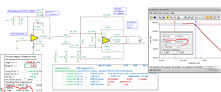
here is this total file,
OPA828 higher Q Zt stage plus FDA MFB stage.TSC
And here is the Zt output impedance, yes it is going through 10ohms just before Fo,