This thread has been locked.

If you have a related question, please click the "Ask a related question" button in the top right corner. The newly created question will be automatically linked to this question.

INA128: Low Frequency Noise

Part Number: INA128
Other Parts Discussed in Thread: INA121

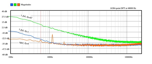
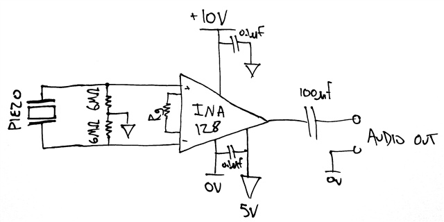
I am trying to amplify a piezo element using the INA 128. The output contains quite a lot of low-frequency noise that seems to depend first on the gain and second on the capacitance of the piezo element. My circuit is shown in the first image below. I tried a brass piezo disc with capacitance around 18 nF, and separately a plastic piezo film which is about 1.2 nF. I connected my circuit to an audio interface and recorded the noise with a few different gains and plotted the results in the second image below. Each plot in the image is the average of 50 samples. Do you know the cause of this or how to mitigate it? I have tried a variety of power supplies, 2 separate audio interfaces, and I have measured the piezo elements using other amplifiers and none of these seem to be the source of the noise.
  • Hi Michael,

    the INA128 shows a noise current density of 0.9pA/SQRT(Hz) at 10Hz. Across a 6MOhm resistor this creates a noise voltage density of

    0.9pA/SQRT(Hz) x 6MOhm = 5400nV/SQRT(Hz)

    which is huge compared to the noise voltage density of INA128 of 10nV/SQRT(Hz).

    With such a high source impedance you should urgently choose an OPAmp with a low noise current density.

    And not to forget the 450nV/SQRT(Hz) thermal noise of a 12MOhm resistance.

    Kai

  • Hi Michael,

    As far as I see, you power the inamp from V-=0V and V+=10V, the reference input is set at 5V and the 6MOhm resistors are connected to 0V. Am I right?

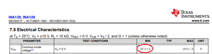
    If so, then the input common mode range ( > (V-)+2V) seems to be violated, and you can get odd behaviour.

    As Kai pointed out, the thermal noise of the resistors and the noise current generates large voltage noise at the differential inputs. This source is shunted by the capacitance, so a lowpass filter is formed whose corner frequency depends on the capacitance.

    Zoltan

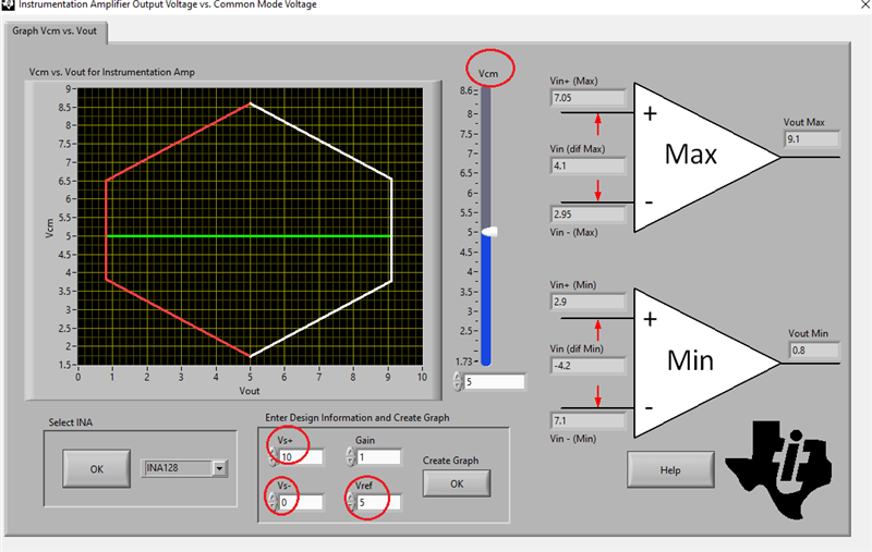
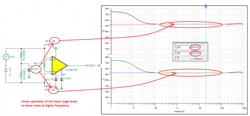
  • Adding to other comments, the INA128 linear input range is shown below.

    However, it changes with supply voltage, Gain, and Vref BUT you may use Analog Engineer Calculator to determine its linear operation - see below.  In order for your circuit to work, you would need to lift the Vcm to 5V or use dual +/-10V supply.

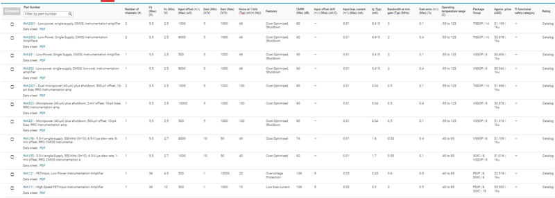
    6M resistor will dominate the noise at low frequency in bipolar input INA's.  See alternative part below with FET input and thus lower current noise.

  • Hi,

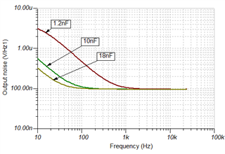
    Although the 6M resistors generate large noise, due to the capacitor it is filtered. The thermal noise of a 6M resistor can be considered as a voltage generator with output resistance of 6M. Therefore it is passed through a lowpass filter. The corner frequency is quite low due to the high resistor value. I’ve made a simulation to illustrate this using different capacitor values (and used 5V common mode voltage at the inputs):

    Using 18nF the thermal noise is not the dominant source above about 50Hz.

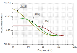
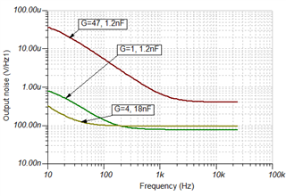
    It can be surprising, but according to the above, higher resistor value can even mean smaller noise above a certain frequency. See the plots below (G=47, 1.2nF).

    This is, because thermal noise amplitude increases as a square root of the resistance, while the corner frequency is inversely proportional to it. So factor of ten means about 3.1x higher noise, but 10 times lower low pass corner frequency. However, at low frequencies the current noise can dominate, since it is not white noise.

    I’ve also made simulation for the original configurations, it looks quite similar to the measurement result:

    I hope I could help to clarify the situation.

    Best wishes, Zoltan

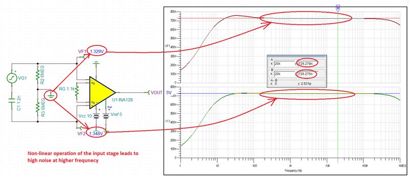
  • I was more concerned about the current noise of the bipolar input INA128 being converted across 6M resistors into thermal noise than the thermal noise of 6M resistor itself. The thermal noise of 6M is about 310nV/rt-Hz whereas the 0.3pA/rt-Hz input current noise converted into thermal noise across the 6M resistor is 6 times higher - about 1.8uV/rt-Hz. However, it will in fact get filtered out at relatively low frequency due to LP filter formed by 18nF input cap and 6M resisters.  All in all, I believe the main source behind the noise you see is the non-linear operation of the INA128 input stage - see below.

    If you lift the Vcm into its linear range between 2V to 8V (for 10V single supply), the higher frequency noise decreases significantly - see below.

  • Just to clarify -- the 6M Ohm resistors are connected to 5V, not 0V, apologies for my unclear sketch.

  • Thanks for the alternative part numbers this is very helpful

  • Thanks for this, this looks exactly right. 

  • Hi Michael,

    again, the input noise current density is the major noise source here, not the resistor noise.

    I have tried to perform a noise simulation with the TI's external noise voltage and noise current generators which I adapted according to this training video:

    https://training.ti.com/ti-precision-labs-op-amps-noise-verifying-noise-model?context=1139747-1139745-14685-1138803-13844

    As the below simulation shows the simulated noise current density is slightly higher at 10Hz compared to the curve in the datasheet, but still acceptably precise:

    The following simulation shows the noise voltage density at the output "Vn_out" while taking into calculation the resistor noise of a 6M resistor (plus a 0F or 2.4nF cap in parallel), the input noise voltage densitiy of INA128 and the input noise current density of INA128. The gain is still 1V/V:

    Then with a gain of 47V/V:

    And the accumulated noise is:

    For simplicity only one 6M leg was simulated. Provided the input noise currents of both inputs of INA128 are uncorrelated, I would estimate a total noise at the output of your circuit of about 1.414 x 1.78mVrms = 2.5mVrms over the 1Hz...100Hz band. The simulation says that the noise will increase even furtherly when you extend the band below 1Hz.

    Kai

  • Thank you so much for this. This is really helpful, I have learned so much from this. I've ordered a few INA121 which have much lower input current noise (1fA/sqrt(Hz) at 1kHz) and look like they will otherwise work for my application. Once they arrive I will repeat my measurement and post it here incase it helps anyone else in the future.

  • Hi,
    I also thank Kai and Marek for their instructive posts! 
    I’ve repeated the simulations using the INA121 you’ve ordered.
    Different capacitance values:


    Different resistance values:


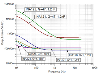
    Comparison of the two inamps using the values of the experiments:


    I also wish you good luck!
    Zoltan

  • I received an INA121 in the mail today and repeated my experiment, comparing it to the INA128. The result is below. It matches Zoltan's simulation perfectly. The noise performance is much better, I think this is going to work for my application. Thanks everyone! 

  • Hi Michael,

    these are good news Relaxed

    Kai

  • Thank you ALL.  I'll close this post.  Happy Holidays!