This thread has been locked.

If you have a related question, please click the "Ask a related question" button in the top right corner. The newly created question will be automatically linked to this question.

LM311: LM311DR operating frequency is unstable

Part Number: LM311
Other Parts Discussed in Thread: LM339

Dear team

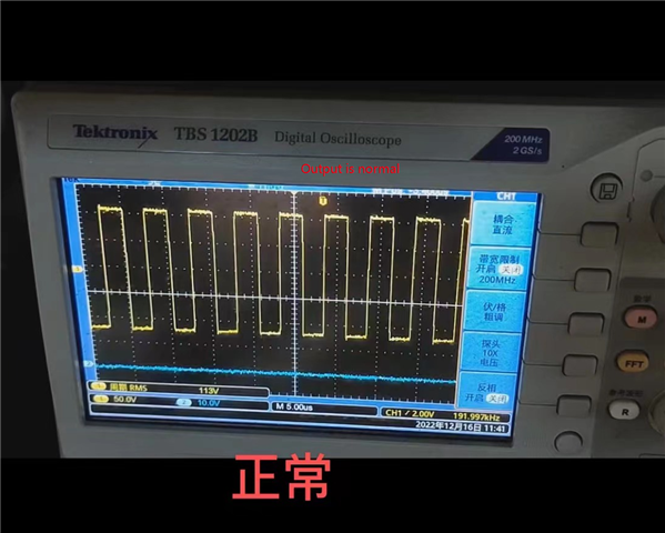
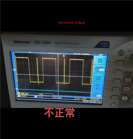
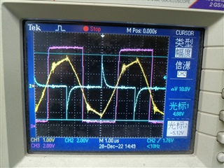
We used two batches of LM311DR, but the working frequency of one batch was unstable.

The normal working frequency was 192KHZ, but it sometimes ran to 96KHZ. Attach test pictures and videos.

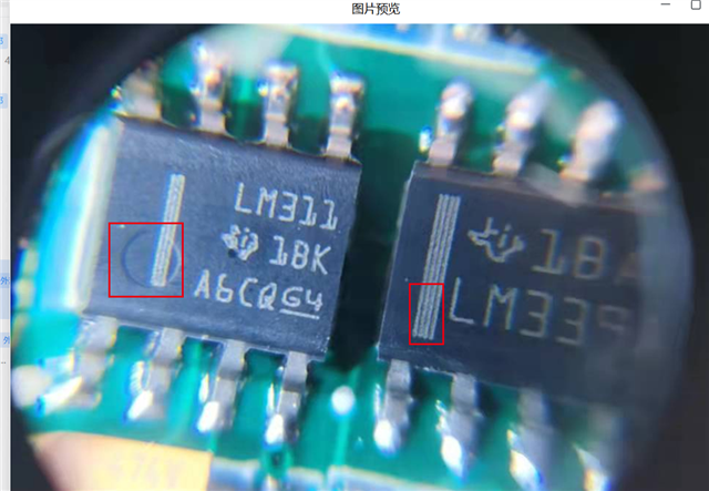
We checked their top marks, and polarity points and lines appeared on the equipment with unstable output frequency.

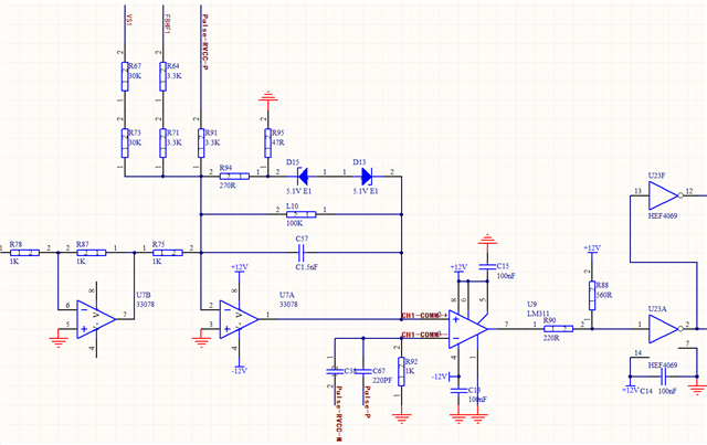
How should we debug the product? Please help provide professional advice, thank you

  • Hi,

    please show a schematic and say something about the input signal.

    Kai

  • Hello User,

    As Kai said, we need a little more information. Such as a schematic, showing supply and expected input voltage ranges.

    What is being demonstrated could be from several sources.

    A scope photo showing the supply voltage, both inputs and the output of both "good" and "bad" operation to compare.

    Is this a new design, or an existing design?

  • Hi  Paul

    Please refer to the schematic.

    In addition, I provided pictures of the top marks of two batches of products. The products with abnormal output frequency display two kinds of polarity marks: line and point. What is the reason?

  • Hi,

    I would not directly connect pin 5 and pin 6 of LM311 to the supply voltage. This will unwantedly shift the operation point of input stage. I would leave them unconnected.

    Also, are you shure that you don't violate the common mode input voltage range at the inputs of LM311? See section 6.3 of datasheet.

    Kai

  • Hi,

    What are the input voltages seen at the comparator? (pin 2 and 3).

    The circle and lines on the marking indicates the orientation of the chip and where pin 1 is. But it looks like the chip on the right is the LM339. is that correct?

  • Closing this thread as we have not heard back. Feel free to reply back if you have any updates

  • Hi ,
    Sorry, the reply was late
    The results of our retest are shown in the picture: 
    Pin3 (blue), maximum voltage+4.88V, minimum voltage - 5.12V, 
    Pin2 (yellow), maximum voltage+2.08V, minimum voltage - 2.2V, 
    Pin7 output pin (purple), maximum voltage+12.0V, minimum voltage+0.88V.
    Please help give suggestions,thanks.
  • Hi,

    it seems that the mistriggering has to do with the blue needle pulses. Either the pulses arriving pin 3 of LM311 are higher than shown in the scope plot and exceed the allowed common mode input voltage range of LM311 or they inject insane current spikes into signal ground via R92 and cause huge ground noise and by this mistriggering or the fast edges of needle pulses capacitively stray-couple into pin 2 of LM311 and cause mistriggering.

    Increasing R92 to 10k and decreasing C67 to 22p can help to decrease the current spike running into signal ground. Using a solid ground plane can help to decrease the ground noise caused by the needle current spikes. Inserting RC low pass filters filters with a small time constant at both inputs of LM311 can help to minimize the cross-coupling between the inputs. Start with 100R and 22pF.

    Another cause of trouble can be instability of U7A: Everytime a needle pulse is cross-coupled into the output of U7A a ringing could take place causing mistriggering. Here the above RC filters will also help by isolating the output of U7A from the needle pulses.

    Kai

  • Thanks Kai for your excellent support

    If further support is required, we will review once we return from our holiday break on January 3.

    Chuck

  • Closing this thread as we have not heard back.