


Other Parts Discussed in Thread: TLV9062, , OPA392
I was doing something else on a different part and noticed a whole string of newer little design references in the support tools. One of those, the MFB design, is onne I have developed extensive tools for and drilled down a bit on it. Just documenting before I close all these down and move back over to something else.
This is the reference design in question and while I was looking I think at the OPA392 for a photovoltaic app, the examples seem to be using the TLV9062 (dual) but I will use the single TLV9061,
https://www.ti.com/tool/CIRCUIT060012
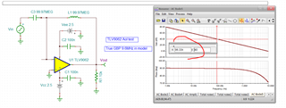
Before we look at the MFB, I always check the model GBP, actually about 9.6MHz vs the spec 10Mhz - pretty close actually relative to a lot of TI parts. It is best to look at the 40dB Aol point (single pole region) and take that times 100X, the 0dB crossover moves around a lot part to part due to high F poles/zeroes.
And this file,
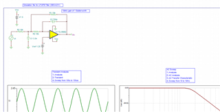
So here is there original MFB design for 10kHz, gain of -1 and Q=.0.707, ok I suppose, noise dominated by R value selections,
And this file,
10kHz Butterworth MFB example.TSC
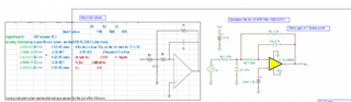
Here are some improved RC solutions for the same filter,
And this file,
10kHz Butterworth MFB improved RC.TSC
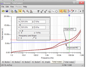
The output integrated noise drops about 20% through 100kHz, this is one of the important plots,
And a little more discussion in this file,
Some testing on an example 10kHz butterworth gain of 1 MFB using the TLV9061.docx
