This thread has been locked.

If you have a related question, please click the "Ask a related question" button in the top right corner. The newly created question will be automatically linked to this question.

INA240-Q1: INA240A1-Q1

Part Number: INA240-Q1
Other Parts Discussed in Thread: INA240

Hello Team,

I am using INA240A-Q1 IC in my project.

Based on the IC datasheet specification, IC common mode voltage is -4V to 80V.

I am planing to use reverse protection diodes before the Rs resistor, So it will protect the IC during reverse voltage conditions 0f -12V or -24V (operating voltage is 12V or 24V).
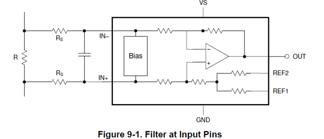
Is it ok to use schottkey diodes before /after the Rs resistors?

If i use Schottkey diode then is it impact gain the accuracy of the IC?

Regards,

Giridhar.

  • Hi Gridhar,

    what will be the current through the protection diodes? Do you need to add a current limiting?

    Kai

  • Hi Kai,

    Thank you for the reply.

    I am using Rs (Series resistors) for Common mode and differential mode filtering purpose only. 

    I don't have any current limiting restrictions for this circuit.

    Regards,

    Giridhar.

  • Hi Giridhar,

    you mentioned that -12V...-24V can arrive the inputs of INA240. When you would mount protection diodes at the inputs to prevent the INA240 from being damaged by negative going input voltages, what current would flow through the protection diodes then during negative going input voltages?

    Where are the negative input voltages are coming from?

    Kai

  • Hi Giridhar,

    Under normal working condition, the diodes can probably be ignored other than leakage currents. If the diodes are placed before Rs resistors (next to Rshunt), then this shouldn’t be an issue. But this might not be a viable option.

    It is probably better to place the diodes after Rs resistors, next to the INA240 input pins. Rs can then limit the reverse current. You can use equations (1) and (2) in section 9.1.1 of the datasheet to estimate the error for any given Rs. I'm afraid Rs might be quite large due to current limiting requirement.

    The other potential impact comes from the mismatch of diode leakage current between two diodes. This mismatch will show up as an input offset voltage, and equal to the current mismatch multiplied by Rs.

    Regards, Guang

  • Hi Kai,

    Thank you for the reply.

    My project requirements (input voltage) are 12V  or 24V battery system. So if we are connecting battery reversely then we will get -12V or -24V to the INA240A1 inputs.

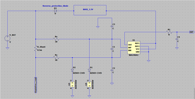
    First, I considered my circuit like below:

    In the above circuit design, During reverse voltage test Rs (Series resistors) are damaging due to more power dissipation (Resistor values are increasing- open failure). If we increasing the Rs value then it will impact the gain error of INA240.  I used Zener diode (BZX84C-3V0) and BAW56 diodes for INA240A1 IC input protection purpose.

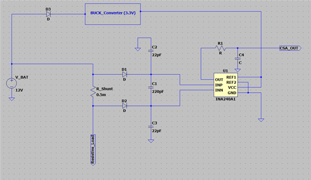
    So for avoiding above issue, I am planing to use diodes like this below circuit

    What are the issues will occur due to above design??  other than diode leakage current problem.

    Regards,

    Giridhar.

  • Hi Guang,

    Thank you for the reply.

    I sent reply to Kai Klaas69 post.

  • Hi Giridhar,

    ok, we are talking about a permanently reversely connected battery. This means that you would have to massively increase the Rs in order to keep the unwanted short-circuit currents acceptably low. You could mount a polyfuse (which is a PTC resettable fuse) in series to each Rs. Or a reverese protection diode in series to the battery, similar to D3.

    Your second approach with the two diodes being connected between the shunt and the inputs of INA240 will unfortunately not work because of the uneven voltage drops across the two protection diodes. Also, this approach will eventually conflict with the input bias currents flowing out of the INA240 which no longer see a path to signal ground then.

    Kai

  • Hi Giridhar,

    Here is a reference design for reverse polarity protection. Can a similar system-level approach be adopted for your application?

    Regards, Guang

  • Hi Guang,

    Thank you for the reply and support.

    For me this reverse protection circuit not possible to implement in the before shunt resistors.

    I will check the poly fuse option & other methods.

    Regrads,

    Giridhar.

  • Hi Kai,

    Thank you for the reply and support.

    My product requirement for reverse voltage test duration is 60sec ± 10 sec only.

    I will check the poly-fuse option for my design for avoiding damage of components.

    Reverse protection diodes method: My application having high current requirement like 100A to 300A. So not possible to use reverse protection diodes.

    Regards,

    Giridhar.

  • Hi Giridhar,

    Sounds good, please post back if we can be of further help in the future.

    Regards, Guang