Hi team,
Customer has strange behaviours on a INA240A2 product from brocker.
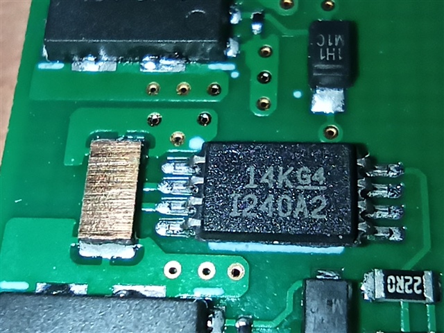
Can you tell us what is the signification of 14K G4 on the top case ?
This thread has been locked.
If you have a related question, please click the "Ask a related question" button in the top right corner. The newly created question will be automatically linked to this question.

Hi team,
Customer has strange behaviours on a INA240A2 product from brocker.
Can you tell us what is the signification of 14K G4 on the top case ?
Juan,
14KG4 are internal markings corresponding to various information including date code as well as site of manufacture. Can you share a bit more as to what the customer is seeing with the device here?
Hi,
Juan posts for me.
The output central point of the INA240 is false : when no current is present, the output voltage is not Vdd/2. We find 0V or 2V for example. The output is OK when INA240 is changed. We find this behaviour only on 14KG4 marking.
Can you tell us what 14KG4 means ? or marking explanations ?
Thanks,
Thibault,
As I mentioned above, these correlate to internal date code markings for the part in question.
The 1 designates year and is deciphered to mean 2021.
The 4 designates month and is deciphered to mean April.
The K designates manufacturing site, and is deciphered to mean Malaysia.
The underscored G4 is a specific mark to denote the IPC/JEDEC standard that the device is built to.
So, in summary, these markings mean "this device was manufactured from a lot in April 2021 in Malaysia."
Hi,
Thanks for the date code information.
Have you seen this strange behaviors on this product in the past ?
Regards,
Thibault,
This is not an expected behavior of the INA240. Is it possible to see a schematic of the system here?
Hi,
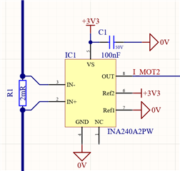
Please find the schematic, a simple RC filter near the UC is missing.
the layout :
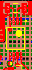
All seems to be well done for me.
Other question about marking, what is the bottom marking explanation ?
Thanks,
Thibault,
I am in agreement that nothing from the schematic jumps out here. The layout seems fine here as well.
Regarding the bottom marking, check out Thomas' reply here. These correspond to factory processes for our internal use for traceability.
One more question here: when you say "no current is present," how are you achieving this? Are you opening the load line of the INA240? This could potentially be causing the issue if so. The INA240 uses the internal bias currents of the front end to power itself, and as such requires this current to maintain linear behavior. If these currents are not allowed to flow through the device, they may exhibit nonlinear behavior. Can you confirm the device is receiving the necessary current on the front end when this is occurring?
Carolus,
Thanks for the quick reply.
My application is like this one :
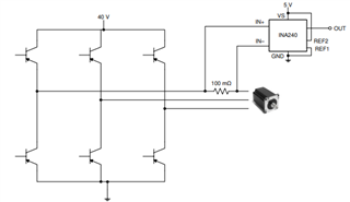
We test the INA output when bridge is off, and error occurs if Vdd/2 is not present (at x %).
So in theory, no bias current. What is the need for the INA240 ? nothing written in the specification.
How make this polarization in a full bridge ?
Regards,
Thibault,
Let me discuss this with a member of my team and I'll circle back. Inline measurement should be ok here, but there may be an issue when the FETs are deenergized.
Thibault,
Thanks for your patience. I spoke with my colleague and verified that typically the leakages of the FETs in an online application should be enough to ensure the INA240 maintains normal operation in this configuration. Inline current sensing is a standard application for this type of device.
I misunderstood above when you said "The output is OK when INA240 is changed." I originally interpreted this as the device inputs being changed, but I see now you mean you swapped out the actual device and saw a correction. How many devices have you observed with this issue? Once you swapped the INA240, did you swap the original part back to see if this issue persisted with the part, ie, an ABA swap?
Hi,
Just tested a ABA swap in the same testing condition, the bad output value follows the component.
Thibault,
It sounds like the component may have become damaged in some way. Have you seen this behavior on more than one unit?
Thibault,
And as you said, all 5 pieces are reportedly from the same "14KG4" lot?
Have you tried testing the devices in a separate environment to confirm that its not some marginal system issue, such as on an INA240EVM? Sorry for the constant questions just trying to get a full picture here.
Carolus,
Yes, 5 failed pieces have 14K marking.
I have tried devices on a few boards. However, I command the INA240EVM in order to try on it next week.
Thibault,
Got it. Can you share how bad the reference is deviating on these parts from the expected ideal here? I am sharing the details with our test team to try and dig further into this. If necessary, would it be possible to work with Juan to return a few of these units to us for analysis?
Hi Carolus,
My contact is now Giorgia NAVARRA, no problem to arrange a analysis.
The output is not at Vdd/2 as expected but from 0.5V to 2V. A test blocs the system at startup when it occurs.
Regards,
Thibault,
I have reached out to Giorgia to see if we can get the return process started. If you perform the test we discussed on an EVM in the meantime, please let me know how that goes.
Hi Carolus,
Unfortunately the pieces don't come from official distributors, so the return process is unavailable.
I made tests on the INA240Ax evaluation board, without success... I think the problem comes from the high dV/dT on the full bridge, the INA240 doesnot support this. I can't minimize it without break the MOSFET.
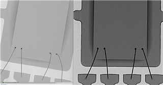
In the meantime, we made RX on official and failed product (respectively grey and black) : the angles (below bounding wires) are not really the same, it seems more "flared" on failed product.
Thibault,
If the problem persists on the EVM, the units are indeed most likely damaged.
Can you elaborate on the high dV/dT here? What is the nature of the switching waveform (amplitude, frequency, etc)
Hi Carolus,
As described above, INA is in serial with the motor on a full bridge.
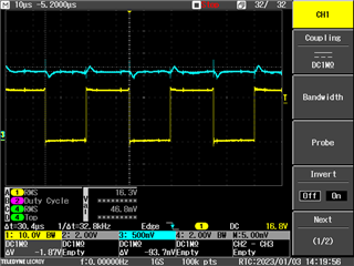
Current measure is not the worst below, frequency is 33kHz.
Thibault,
The INA240 should be capable of such a waveform. Typically, with the PWM rejection scheme, the device is able to handle up to 100kHz with minimal THD, and that is the crux of the argument, higher dV/dt typically manifests as distortion on the device as the PWM rejection algorithm selectively removes high frequency harmonics, but this does not typically result in damage to these devices provided the abs maximums are not violated.
Coming from unofficial channels, its possible that these may be counterfeit devices, or that they were stored or mishandled in some way that has compromised their integrity. As I said above, given the fact that the symptom persists even on the EVM, I would conclude these are most likely damaged units.