This thread has been locked.

If you have a related question, please click the "Ask a related question" button in the top right corner. The newly created question will be automatically linked to this question.

LMV761: LMV761 Not Responding

Part Number: LMV761
Other Parts Discussed in Thread: TLV3601, LMV7219, TLV3201, TLV3501, TLV3603

Hello

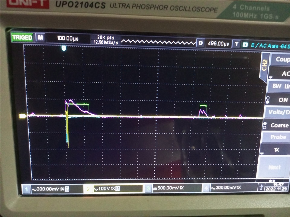
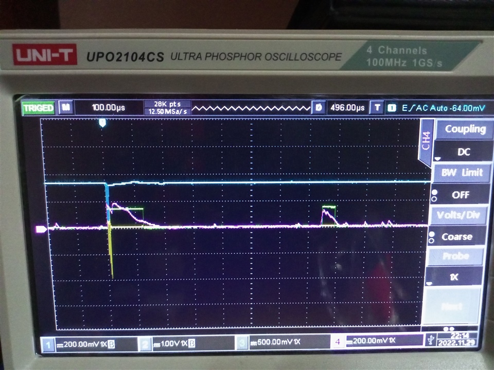
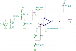
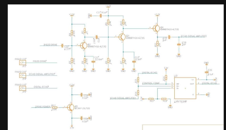
I am using LMV761 in our project for ultrasound level sensing device. The IC is used to detect the echo signal from the amplifier stage of the circuit. 

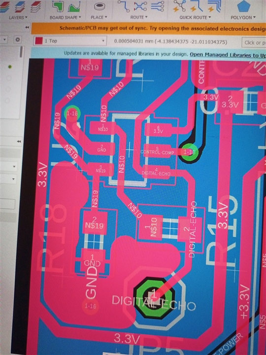
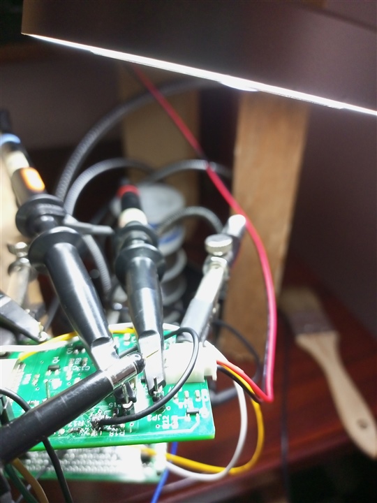
The IC is not responding unless I touch the output with the probe of the oscilloscope (the cylindrical part as seen in the pictures). When I touched the output pin with the probe section part, it starts operating. I don't know what is happening. I have uploaded the PCB part of the IC on the circuit. 

Need some help here!! 

  • Hello Bisso,

    Can you please provide the full schematic, showing the entire input stage and sensor? I see a lot of "NS" (No Stuff) resistors...

    My guess is that you have a AC coupled input and are not providing a DC bias path - which the scope probe provides when attached.

  •  Hello @paul. Thanks for the reply. Hope it can be helpful 

  • Hello Bisso,

    What are the values of R15, R16, R17, R18 and R19? What are the expected input voltage ranges of ECHO_SIGNAL_AMPLIFIED and DIGITAL_ECHO?

    Remember that the LMV761 is not a R-R input and all input voltages must be at least 1.2V below V+ (or +2.1V input max max on a +3.3V supply).

    Do you have any scope photos?

  • The Value of Resistors:

    R15 = 56k

    R16 = 5.1k

    R17 = 13k

    R18 = 3.3k

    The Expected voltages range of the Echo_Signal_Amplified is between 1.5 v and 0.4v

    I am uploading a scope image when we succeed to activate the comparator using the probe cylindrical section part. 

  • The Purple : Echo_Signal_Amplified

    The Green Green heartGreen heart : Output signal from the comparator after I touch the output lead with the scope

    The Yellow : The piezoelectric output 

    The Blue Large blue circle: The driving signal for the piezoelectric sensor. 

    I hope it will help!!

  • Hello Bisso,

    From what I see, the threshold at the -IN input is about +670mV.

    Unfortunately, your scope photo scope photo seems to be AC coupled, so I cannot see the DC relationship between the input signals and the threshold.

    What is the "DIGITAL_ECHO" voltage range? It is providing the DC bias.

    It looks like the input to the comparator is AC coupled, through C15 and C16, which creates a capacitive divide-by-two divider. So the input voltage would be centered ± around ground at half amplitude. Did you intend that? Where is the sensor?

    Can you capture a photo of the +IN, -IN and output on a common reference with DC scope coupling so that we can see the true relationship of the signal levels?

  • I have activated DC coupling for all the channels!! This is the results. 

  • The capacitor C15 and C16 was primarily used to filter all noise and ripple in the echo signal, and smoothing the signal for the comparator to be not driving by noise signal. 

    I was not aware of the capacitive divider!!

  • What do you think might be the issue from your analysis? Because I have not been able to figure out what cause this type of operation of the IC. Don't have much experience in electronic design! 

  • Bisso

    Thanks for the additional information. We’ll review tomorrow and get back to you. 
    Chuck

  • Thank you!

    I am waiting! 

  • Hello Bisso,

    The main problem seems to be the cap-coupled input and the positive feedback from the output through R15.

    The scope photos color is a bit washed out, so a little difficult to tell the waveforms apart. Also, it seems that your probe settings are 1X, but you appear to be using x10 probes, so the measured voltages are off by 10x.

    DC-wise, the output is pulling DIGITAL_ECHO_AMPLIFIED between 0V and 3.3V through R15.

    Since this is the positive input ,when the positive input is above the negative input (670mV reference), the output will go high. So you have created a latch, and are "resetting" it by shorting the output low.

    For hysteresis (positive feedback), there needs to be a low source resistance for the divider to work against. I'm assuming R15 and R16 are for the hysteresis. The problem is that the capacitors do not provide a solid, low impedance DC source for R16.

    What needs to be done is to bias the ECHO_SIGNAL_AMPLIFIED to a point below (or above, depending on your signal and polarity) the 680mV threshold.

    So remove C16, and create a voltage divider (similar to R17 and R18) to set a DC bias point just slightly below the R17/18 voltage (as shown by R1 and R2 below).

    Also notice I changed R15 to 560k, which is more appropriate for hysteresis. With properly functioning hysteresis, you should not need the bruit-force filters.

    Of course, you will need to adjust these thresholds to your requirements.

    Simulation is attached..

    Bisso.TSC

  • Thank you, Paul, for your feedback, Let me try it out!
    Get back here with detail results after applying these suggestions!! 

    Also, You have seen the PCB Layout, it is true that I haven't respected the requirement from Datasheet, I hope it is not also one of the causes of the IC failure!! 


  • Hello Bisso,

    This was a basic design problem. Layout is not the problem. I do not see anything "dangerous" that could cause damage.

    You may be able to shoe-horn one of the two recommended resistors onto C16's old pad. You may also want to start without R15 so you can dial-in your levels.

    And as I warned, be sure that the input voltage range on either input pin is between 0V and 2.1V, or you could have false outputs.

  • Thank you very much Paul!

    Also, can you recommend like similar comparators in the same package that can do the job?  That will help me for further development!

    I still implementing your suggestions!! 

  • Hello Bisso,

    Do you need the shutdown? Does it need to be in the same pinout? Can you use a dual? Any package preferences? Prefer low cost or better performance?

    There are several options. See out the LMV7219, TLV3201, TLV3501, TLV3601. There is also the TLV3603, which has adjustable internal hysteresis (wont need R15).

  • 1. I need SHutdown unless it has a low-quiescent current 

    2. Not necessarily the same pinout

    3. No a Dual

    4. SOT-23-6

    5. Low Cost

  • Thanks!! I made the change you suggested in the circuit with the voltage divider, as well as with the R15, then I increased the Vref to suit the thresholds. 
    I have shifted the C16 behind the voltage divider because it is needed because of my programming setup to detect only the one pulse after the first one at the start!! 

    Thank you Paul for your great help!!!