This thread has been locked.

If you have a related question, please click the "Ask a related question" button in the top right corner. The newly created question will be automatically linked to this question.

INA220: ina220 - measured current value is higher than expected

Part Number: INA220

Hi TI team,

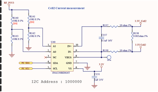
We are using INA220 current sensor circuit in our design and the circuit is as shown below.  It has been observed that there is 100mA to 200mA difference between the measured value and applied load current.(Higher the load, larger the difference in measured current value).

INA220 Circuit: 


Measured current values:

Applied load Current sensor Measured value 
300mA  410mA
400mA 520mA
500mA 645mA
600mA 775mA 
700mA 885mA 
1000mA 1200mA
5000mA 5999mA

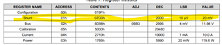
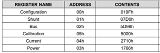
Register Configuration is set as per datasheet (Since our circuit is same as Figure 30 of datasheet):

Can you please support us on resolving the same?

Regards,

Vidhya

  • Hello,

    The schematic looks fine. What pull-up resistors values are you using for the SDA and SCL and what speed is the I2C communication?

    Can you verify the Vshunt register is the Vshunt expect on the shunt resistor? Mainly compare the Vshunt register on the INA220 to the voltage across the shunt.

    Regards,

    Cas

  • Hi Cas,

    Pull up value is 10K and i2c speed is 400kHz. Shunt register value set to 07D0h

    Regards

    Vidhya

  • Hello,

    You cannot set the Shunt register that must be read by you. It is a read only register that will give you the value of the voltage produced across your IN+ and IN- pin. I was asking if you could verify that when you read this value it is the same as a measured value at the input pins of the INA220. This will indicate that you may have a wrong calibration factor in the calibration register.

    I will lay out the steps for you to calculate the calibration value for the current register. 

    First calculate this: 

    Then input this value into the calibration register: 

    Regards,

    Cas