This thread has been locked.

If you have a related question, please click the "Ask a related question" button in the top right corner. The newly created question will be automatically linked to this question.

LMP7721: LMP7721

Part Number: LMP7721
Other Parts Discussed in Thread: LM4140

In the datasheet it is mentioned that cleanliness and moisture play a viral part in the performance of LMP7721 and it seems to be its very critical for the performances. My question is how to protect it from moisture and other impurities when using in application as conformal coatings are also not recommended. Thanks in advance.

  • Hi Ayodhya,

    whether cleanliness and moisture is "very critical for the performance", as you say, mainly depends on your application. This has more to do with your application than with the LMP7721 itself. Or by other words, the LMP7721 is not a critical part by itself.

    In less critical applications a conformal coating or a potting can be used, by prefering non-hygroscopic materials. In more critical applications the printed circuit board may sit in a hermetically sealed enclosure with a drying agent (freshly activated silica gel or similar) placed in it.

    Can you tell more about your application?

    Kai

  • Hi Ayodhya,

    The LMP7721 is a femto-amp level input bias current amplifier that is designed for applications with very high input impedances and very small measurement currents. Applications with very high impedances are sensitive to material contamination such as flux residues or oils, as these contaminants become surface-level conductive paths for current to leak into high-impedance nodes. High-impedance applications are also very sensitive to humidity and moisture as moisture can affect the dielectric and insulation properties of the PCB and component materials.

    As Kai mentioned the "sensitivity" to contamination and moisture of your application depends on your performance requirements for Input bias current (IB), the impedances seen by the LMP7721 input traces, and the material properties of your PCB and the components placed at high-impedance nodes. 

    Conformal coatings are not recommended for femto-amp level designs as these can become yet another surface-level leakage path that will degrade IB performance. Enclosing the amplifier and feedback components within a grounded RF shield can help protect sensitive nodes from moisture and material contamination, as well as reducing EMI and external noise coupling. After the PCB is assembled and cleaned, any moisture absorbed by the board during the cleaning process must be baked out in a high-temperature oven for at least two hours. Moisture barrier bags with desiccant packs can be used for storage of the circuit boards after completing the PCB baking process. If your application presents a very humid environment in which performance is degraded due to moisture absorption, you may consider placing the PCB in a hermetically sealed enclosure or an enclosure with a controlled humidity.

    Regards,

    Zach

  • Thank you kai for the quick response. I'm using this in a PH measuring instrument. So it is the application. I asked this question because the readings are not stable and its very volatile. If you know any other reasons which can cause this, can you explain please about it also.

  • Hi Ayodhya,

    The LMP7721 is a femto-amp level input bias current amplifier that is designed for applications with very high in

    Thank you Zach for the quick response. I have the same question to ask from you also. I'm using this in a PH measuring instrument. So it is the application. I asked this question because the readings are not stable and its very volatile. If you know any other reasons which can cause this, can you explain please about it also.

  • Hi Ayodhya,

    if the printed circuit board is dry and clean during the instable readings, then there may be another cause for the malfunction?

    In most cases the PH sensor is damaged when a PH measurement is doing wrong. This is my experience. PH sensors are extremely sensitive and vulnerable. For instance, forcing a DC current through the PH sensor like when connecting an Ohm-meter across the PH sensor can damage the PH sensor. So, it could be a good idea to check the circuit with another PH sensor from which you know that it is not damaged.

    Another cause could be a circuit problem. Can you show a schematic of your circuit?

    A much simpler cause could be a connector problem...

    Kai

  • Hi Ayodhya,

    There can be many causes for an electrical circuit to produce an unexpected output voltage. Can you provide your circuit schematic and a photo of your test set-up? What is the impedance of your PH sensor? If you are using a commercial off-the-shelf PH sensor can you specify the part number? Based on your PH sensor and the solution being measured, what is the expected input and output voltage of the LMP7721? Can you provide an oscilloscope image of your output signal?

    Thanks,

    Zach

  • Hi sorry for late reply. There was a problem in my account. I hope you are still there.

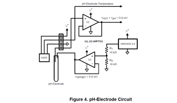
    This is the circuit  we use which is given in the reference by Texas. The impedance of our PH probe is about 380 megaohm. Recently I diagnosed that with the temperature of the IC the reading varies. Is there a way to compensate the temperature in IC when operating. In our region the temperature is bit high about 35 Celsius.

    Thank you.

  • Hi sorry for late reply. There was a problem in my account. I hope you are still there.

    This is the circuit  we use which is given in the reference by Texas. The impedance of our PH probe is about 380 megaohm. Recently I diagnosed that with the temperature of the IC the reading varies. Is there a way to compensate the temperature in IC when operating. In our region the temperature is bit high about 35 Celsius.

    Thank you.

  • Hi Ayodhya,

    Recently I diagnosed that with the temperature of the IC the reading varies.

    Can you give a number? Please specify how much the reading varies.

    Is the voltage variation higher than the maximum temperature drift of LM4140 (10ppm/°C) and maximum offset voltage drift of 4µV/°C?

    Keep in mind that the voltage divider R1 / R2 can also have an impact on the temperature drift of output voltage. Because of that the temperature drift of R1 and R2 should be better than 20ppm/°C to be able to maintain the precision of LMP7721 and LM4140. So, please only take state-of-the-art thin film resistors for R1 and R2.

    Assuming 20ppm/°C for each resistor, 10ppm/°C for the LM4140 and 10ppm/°C for the LMP7721 (4µV/°C equals 8ppm/°C of 512mV) the output voltage will only change by 200µV in the temperature window between 25°C and 35°C. And even a huge and unrealistic input bias current drift of 900fA would give an additional voltage drift across the PH-sensor of only about 300µV, resulting in a total drift of about 500µV when changing the temperature by 10°C.

    Is this what you observe?

    Kai

  • Hi Ayodhya,

    I see you are showing a figure from our application note about designing circuits with PH probes, this is a great reference. However, this is just a figure showing a simplified example of a PH-electrode circuit.

    Can you please provide your actual circuit schematic? If you have an issue with your design I will need analyze the real circuit that you implemented to check for possible errors. Please also provide a clear photo of your test set-up so I may check if everything is wired correctly.

    As Kai said, please specify what voltages you are reading and at which nodes you are taking the measurement. Including your oscilloscope probes and/or DMM test leads in the photo of your test set-up will help us understand how and where your signals are being measured.

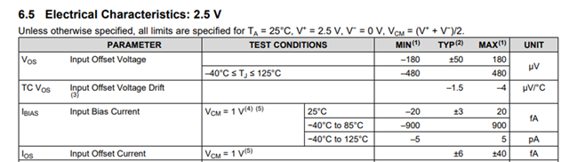
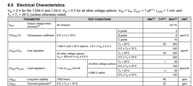
    Kai provided an excellent analysis of the thermal drift errors that could be present in your circuit, however without the actual schematic we cannot know all of the potential errors you may be seeing. 35°C is not considered particularly hot for an electrical circuit and the vast majority of applications will easily tolerate the small thermal drift from 25°C to 35°C (100s of µV worst case from Kai's analysis).

    If you want to look into the thermal drift analysis more, you may find the thermal drift specifications in the "Electrical Characteristics" section of the LM7721 datasheet:

    and the Electrical Characteristics section of the LM4140 datasheet:

    Regards,

    Zach