This thread has been locked.

If you have a related question, please click the "Ask a related question" button in the top right corner. The newly created question will be automatically linked to this question.

INA185: Please review the schematic

Part Number: INA185
Other Parts Discussed in Thread: TINA-TI

Hello TI experts,

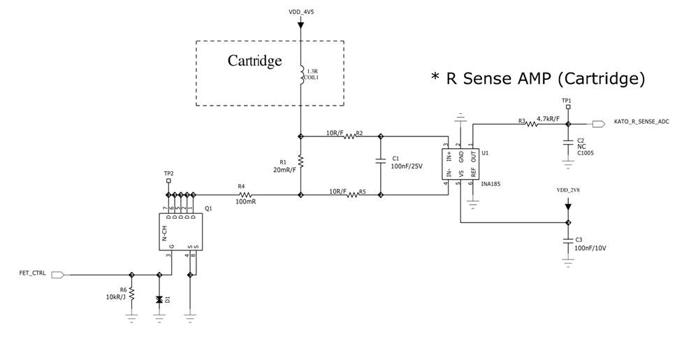
My customer made their first PCB with INA185, could you review the schematic first?

and here is a question,

my customer tested with INA185A2, they found that transient time is about 200us.

1. How can we reduce transient time? can we reduce it by using INA185A1?

2. is there any side effect if we try to reduce transient time?

Please check this issue. Thanks.

Best regards,

Chase

  • Hi Chase,

    when no current is flowing through the coil and the REF pin is connected to signal ground, the INA185 will hang in output saturation and will need some time to recover from this saturation when a current begins to flow through the coil (overload recovery time). Run a TINA-TI simulation with the

    INA185 TINA-TI Reference Design

    Also keep in mind that a big inductance of coil can also make the current slowly rise. This is how an inductance works

    https://electronicspani.com/rise-and-decay-of-current-in-an-inductive-circuit/

    By the way, coils are known to generate a destroying inductive kickback when the current through is them is abruptly turned-off. Have you mounted a free wheeling diode across the coil?

    Kai

  • Hi Chase, 

    The schematic looks good. One suggestion would be to populate C2 which will serve as a charge bucket to help drive the ADC. If implementing this charge bucket, decreasing the R3 value will help with not delaying the output as much. 

    Kai is correct in that the output will take some time to settle due to the inductance, especially if the coil current is initially at 0 A.  

    Cierra

  • Dear Cierra, kai,

    Thank you for your support.

    then the difference of gain (A1, A2...) does not affect to the rising time? Please check it again.

    and one more question,

    By the way, coils are known to generate a destroying inductive kickback when the current through is them is abruptly turned-off. Have you mounted a free qheeling diode across the coil?

    -> I think you mean free wheeling diode. Could you recommend it which has minimal size?

    Best regards,

    Chase

  • Hi Chase,

    again, run a TINA-TI simulation with the

    INA185 TINA-TI Reference Design

    to see the effect of rises time of A1 and A2 versions and the effect of output saturation recovery time.

    The freewheeling diode has to witstand for a brief period the same current that is also flowing through the inductance.

    Kai

  • Hi Chase,

    The bandwidth of the A1 version will be higher than the A2, however the rise time is impacted more by the slew rate. Slew rate is the same for both gains, so I would expect the rise time to be similar. We have a TIPL training video that explains this here: https://training.ti.com/slew-rate-and-bandwidth 

    As Kai mentioned, you should select the freewheeling diode based on the peak current expected.

    Cierra