Hi TI Team,
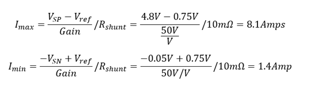
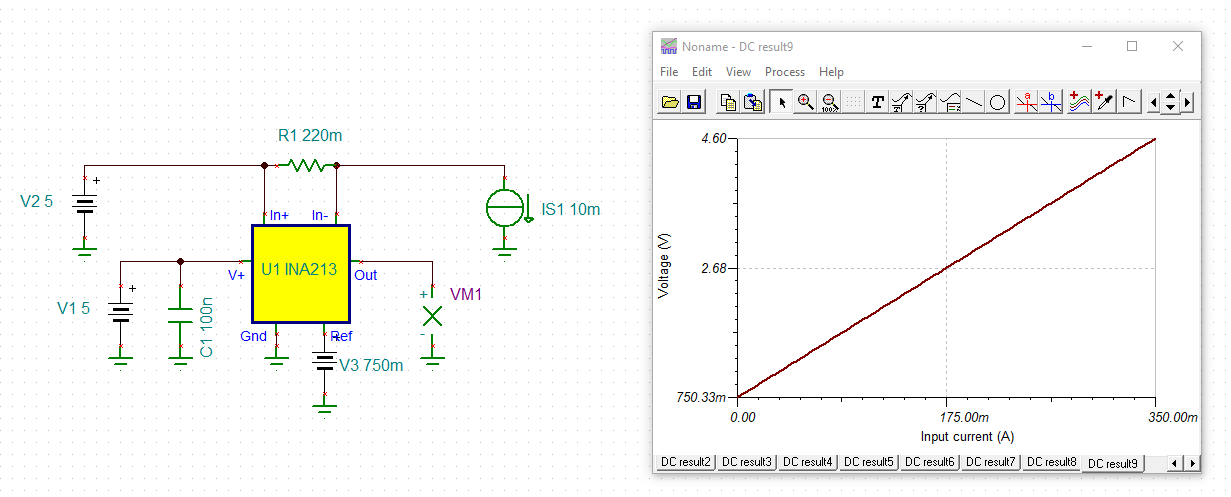
We are using INA213`AIDCKR part in our application. Our requirement is to measure current till 0.35A. what shunt value resistor should I use since the datasheet mentions min drop allowed should be>= 10mV.
Hi TI Team,
We are using INA213`AIDCKR part in our application. Our requirement is to measure current till 0.35A. what shunt value resistor should I use since the datasheet mentions min drop allowed should be>= 10mV.