A related question is a question created from another question. When the related question is created, it will be automatically linked to the original question.
If you have a related question, please click the "Ask a related question" button in the top right corner. The newly created question will be automatically linked to this question.
I need to know the detailed design requirements in your application. For instance, what is application? What are the type of load, output voltage swing, required driving current, etc.? It is doable, but the simulation may provide better understandings, if we are able to meet the application requirements.
Enclosed is a quick example, which I made it up. If you have additional questions, please let me know.
I use this amp to run current through the coils of a voice coil motor. Right now I am using one amplifier to drive it, but I would like to use a bridge circuit to drive a larger current.
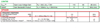
Type of load: coil (10Ω) Output voltage: ±24V Output current: 4A
Question. Why does the reference circuit show the output signal (Vp) of U1 as the input signal of U2? My thought was to use the same input signal to create a bridge circuit using an inverting and non-inverting amplifier circuit.
Are you driving the speaker up to 20kHz in audio application? How critical is the audio application? OPA549 may not be well suited to drive an audio speaker application.
Is output voice coil is 24Vpp? If it is 24Vpp, each half of power amplifier will responsible to driver 12Vpp in amplitude. Please let us know more about the audio application.
Raymond is out for the Chinese New Year. I'll try to follow up on these posts.
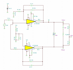
Looks like you have a single-ended input that you need to convert to differential to drive a high power differential (BTL) coil. Raymond used the output of the first stage, and fed to an inverting stage, to create the inverted signal. For this case the total load in the input source is reduced. The downfall is that the phase of the second inverting stage will not maintain exactly 180 degrees as the bandwidth goes up, which will then lead to differential errors at higher frequencies.
Phase errors will result in a common mode signal. Ideally, when there is a perfect 180 degree phase difference, then the common mode gain is zero or very low. As the phase errors increase, then the common mode voltage increases.
In the circuit below, I measured the common mode voltage with a simple resistor divider. When measuring the common mode gain between the two circuit types, there was lower common mode gain for the circuit below (using an inverting and non-inverting stage), mainly due to the phases maintaining 180 degrees..
However, this is a slightly larger solution because of the additional R/C components.
If your system is sensitive to these differential errors, the ideal solution would be to use an Fully-Differential Amplifier to convert the single-ended solution to differential, then drive the load with buffer-connected OPA. However, many times this is not a critical concern, so it is possible both Raymond's circuit and and circuit above would be fine.