A related question is a question created from another question. When the related question is created, it will be automatically linked to the original question.
If you have a related question, please click the "Ask a related question" button in the top right corner. The newly created question will be automatically linked to this question.
Effect of the Input Impedance of the source to the OP Amp
there's no simple answer. It depends on the used OPAmp (whether it has a high input bias current or not), on the intended accuracy (what voltage drop across the 10k source impedance is tolerable) and the oxygen sensor itself (whether it allows any DC input bias current of OPAmp to flow into the output). What oxygen sensor do you want to use?
If you choose a FET-OPAmp or CMOS-OPAmp, then the 10k source resistance of sensor does not play any role, because these OPAmps don't show any relevant input bias currents, usually. And because of that, no input bias current cancelling scheme would be needed either.
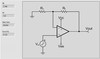
By the way, I would increase R1 and Rf by a factor of ten or so. The values you have chosen seem too low ohmically and may present a too heavy load to the output of OPAmp. What OPAmp do you want to use?
There's another issue: The OPAmp output must fully settlle within the sampling time of MSP430. So, either you choose a sufficiently fast OPAmp or you decrease the sampling time of µC. See the User's Guide of your µC.
Adding to other comments, I would be concern about the high source impedance interacting with chopper amplifier input bias (IB) current spikes, converting them across the high source impedance into voltage spikes. This not only may cause additional noise but also result in an increased input offset voltage.
Having said that, you do not specified required supply voltage or settling time so I'll give you few parts to pick from:
5V supply voltage, fast settling time; OPA392, OPA325 and OPA328 (linear) or OPA387 (chopper)
5V supply voltage, low power; OPA391 (linear) or OPA333 (chopper)
36V supply voltage, fast settling; OPA192 and OPA828 (linear) or OPA182 (chopper)
36V supply voltage, low power; OPA191 (linear) or OPA186 (chopper)
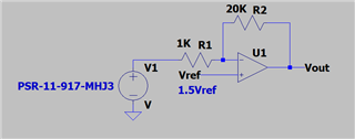
the PSR-11-917-MHJ3 is a member of a whole family of very similarily working oxygen sensors. This sort of oxygen sensor outputs a very small output voltage, here between 8mV and 12mV at 21% oxygen. Actually, these oxygen sensors generate a current which is transformed into a voltage by an internal low ohmic resistor (something arround 100R). This low ohmic resistor is added by NTCs to provide a temperature compensation. So, the source impedance is arround 100Ohm, but not 10kOhm!
To get all the signal voltage out of this sensor, the manufacturer usually recommends a load resistor at the input of amplifier which exceeds 10kOhm. Then, the source resistance and the input resistance form a voltage divider and more than 99% of the signal voltage is arriving the amplifier input. This also means that the error introduced by the voltage division is less than 1%.
Because the mechanism of sensor is the gereation of a current, you should not drive any relevant DC current into this sensor which could compete with the signal current. But this is exactly what you do when biasing the +input of OPAmp with 1.5V and connecting the sensor via a 1k resistor to the -input of OPAmp. Then, you force a current of up to 1.5V / 1k = 1.5mA into the sensor.
I would take an ultra-low input offset voltage OPAmp with CMOS- or JFET-inputs and would connect the sensor to the +input of this OPAmp. Connect the ground terminal of sensor to signal ground. Operating the OPAmp as non-inverting amplifier with a gain of 21V/V (as shown in your circuit) is a good idea. This transforms your sensor signal into an output voltage of 8...12mV x 21 = 168...252mV at 21% oxygen.
If you want to cover the whole oxygen range of 0...100%, this circuit will output a signal of up to 100% / 21% x 252mV = 1.2V. But keep in mind that the OPAmp may not be able to go all the way down to 0V at the output. So, either you restrict yourself to oxygen levels different from very low concentrations, or you should add a small negative supply voltage to the OPAmp. The LM7705 is ideal for this purpose.
Another remedy is to increase the gain of your circuit. Then, less of the signal is lost in the 0V output saturation of OPAmp.