This thread has been locked.

If you have a related question, please click the "Ask a related question" button in the top right corner. The newly created question will be automatically linked to this question.

INA337: INA337 going to saturation

Part Number: INA337
Other Parts Discussed in Thread: LMV321, INA321

Hai,

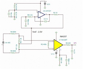
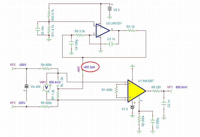
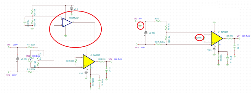
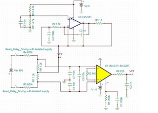
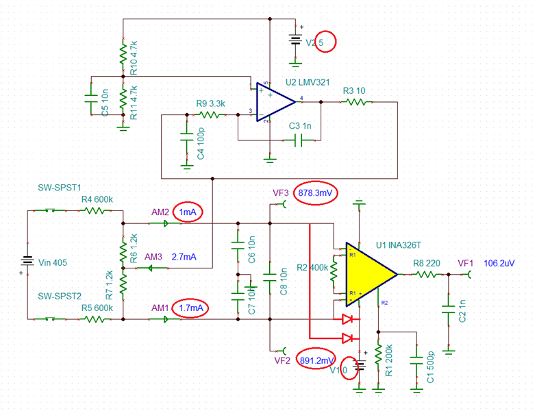
I am using INA337 instrumentational amplifier with gain of 1 for reading a high voltage 405V signal  with resistor divider network as  per the attached schematic. I have added a 2.5V reference for this circuit at input as a common mode voltage.

At normal or most of the time I am  getting a result of 808.3mV at the output of the amplifier but at some cases getting 5V at the output pin. If I Power reset the circuit then it is working normal again. I am unable to understand what could be the reason for this malfunction.

Regards
Venkat

INA337 Simulation.TSC

  • With all the circuitry around LMV321 buffer, I suspect that during power up condition the floating Vin will cause the circuit to get into a lockup state resulting in the VF1 output slamming against the positive rail. 

    Below please find two solutions that should eliminate the problem.

    INA337 Simulation_ML.TSC

  • Hai Marek,

    During the malfunction case I measured the Vref voltage (LMV321 o/p) and it is stable at 2.5V which is the correct voltage as per the design. 

    So I suspect if any other reason for this malfunction.

    Will there be any common mode voltage issue?

    Regards
    Venkat

  • Hi Venkata,

    the INA can also go into lock-up.

    Keep in mind that during power-down the only current path for the high voltage at the input of circuit is the input protection diodes of INA and the input and output protection diodes of LMV321. So, when the high voltage is connected before power-up you violate the maximum input voltage ranges of OPAmps which may result in latch-up or lock-up.

    The lock-up mentioned by Marek sounds very plausible and happens very often in such circuits. Because of this, I would redesign the circuit in a way, that the high voltage at the input of circuit sees a direct path to signal ground. One way to achieve this may be the use of a bipolar supply voltage.

    Kai

  • Adding to Kai's recommendation, if you want to get to the bottom of the reasons behind the issue, in addition to voltages around LMV321 you should probe voltages around INA337 using scope in order to eliminate the possibility of instability (multi-meters shows only rms value).  If the circuit biases up properly as designed, I do not see violation of the input common-mode voltage of either IC - however, the question is what happens during power up sequence.

  • Hi Kai,

    Sorry! I have not informed earlier that I have connected two reed relays(switches) in series with Vin on both +ve and -ve sides. These will be enabled only after 13ms after the 5V supply is available for INA337. So before the HV input is enabled INA337 and LMV321 circuits are powered and stable.

    Venkat

  • Hi Venkata,

    reed relays and most other relays show an unpleasant behaviour: The contacts need a minimum current to reliably turn-on. For very low currents a relay should be used which is designed for so called "dry loads". Such a relay has contacts made of a solid gold layer sitting in an inert gas atmosphere.

    Can you show in the schematic where exactly you have mounted the relays?

    Kai

  • Hai Kai,

    Please find the attached image showing the location of the reed relay (SHV05-1A85-78L3K)

    Regards
    Venkat

  • Hi Venkata,

    ok, at this point a current of 400V / 1200k = 330µA will flow through the relay contacts and the relay may work.

    Kai

  • Hi Venkata,

    You do not specify whether you power both IC's from a single 5V power supply or use separate supplies (V1 and V2 show on your schematic).  But even if you use a single supplies, IC's power-up time may be different - in the case of V2 powering up before V1, this may lead to forward biasing of the INA321 ESD protection diodes as shown below, thus leading to lock-up conditions.

  • Hi Venkata,

    since earlier lock-ups or latch-ups or any other overvoltage events may already have damaged your OPAmps, I would recommend to replace them by fresh ones and check the circuit again.

    Kai

  • Yes, a prudent point, Kai.  Thank you.