A related question is a question created from another question. When the related question is created, it will be automatically linked to the original question.
If you have a related question, please click the "Ask a related question" button in the top right corner. The newly created question will be automatically linked to this question.
"My" approach is originally from the TI's former employee Tim Green:
I introduce a stimulus directly to the input pins of OPAmp and look what comes back via the feedback loop. From the frequency response and phase response I can directly determine the phase margin.
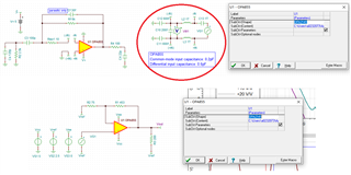
Because the feedback loop is opened at the input pins, the feedback loop no longer sees the input capacitances of OPAmp ("C10", "C11" and "C12" in your simulation). Because of that the input capacitances have to be "mounted" externally.
"L2" and "L3" close the feedback loop for DC and allow the OPAmp inputs to be properly DC biased.
"C13" provides an AC coupling of stimulus without ruining the DC biasing of OPAmp inputs. And because the AC coupling shall be invisible even for the lowest frequencies "L2", "L3" and "C13" are chosen to be "infinitely" high.
The advantage of this a bit more opulent method is that the complex output impedance of OPAmp is also taken into calculation.
By the way, there's a little mistake in your simulation. You have swapped the meaning of "C10", "C11" and "C12": "C10" is the differential input capacitance and "C11" and "C12" are the common mode input impedances.