This thread has been locked.

If you have a related question, please click the "Ask a related question" button in the top right corner. The newly created question will be automatically linked to this question.

TLV7031: selection of comparator for electronic fuse

Part Number: TLV7031
Other Parts Discussed in Thread: TLV9032, TLV1805, TPS1663

Hello everyone,
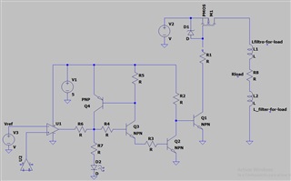
I am designing a typical electronic fuse (unfortunately I cannot find an eFuse that opens the circuit with 11A) I have already designed all the stages, but in the current sensing circuit, I want to place a comparator that activates the base of an NPN transistor, I want to use a TLV7031DCKT but I don't know if it can supply the current I need, will the circuit work well if I use this comparator? I will place a referential image of the design (ignore the values ​​of the components, it is only referential so that you understand the purpose of the TLV7031DCKT) I will place the TLV7031DCKT in U1, because U2 is an INA280A1 current amplifier, which I think is the best option, if you can help me I would be very grateful

  • The specified VOH was measured with a current of 3 mA.

    There are current amplifiers with integrated comparator (usually with active-low, open-drain output).

  • Hi Martin,

    Thank you for reaching out. How much current are you expecting to load on the output of TLV7031? The VOH/VOL levels will be dependent on the current as Clemens alluded to; you can see the relationship in Fig 18-21 of the datasheet which shows the output swing graphs based on how much you expect to sink and source current. 

  • Hi Martin,

    what is the purpose of Q2, Q3 and Q4? Is there a special reason why your circuit is so complex?

    Kai

  • Martin,

    We will wait to hear from you.

  • I really expect to get around 10mA minimum when the comparator circuit turns high, but for a few microseconds, because when transistor Q4 turns on it supplies current to the base of Q3 and to the diode, and the current from the TLV7031DCKT is will reduce significantly. But I observe that at 5mA with Vcc = 5V the voltage drops to 4.78V, so I would expect around 4.5V at the output of the comparator when turning on transistor Q3?

  • Try to make a latching circuit for transistor Q1, because when the current stops flowing after the overcurrent detection, the comparator will supply a low level again and everything will turn back on with the overcurrent appearing again, it's the best I could do already. This is the first time I've designed an electronic fuse, I would have liked to use an eFuse, but I don't know which eFuse could you recommend that works with a voltage greater than 33V and detects overcurrents greater than 11A?

  • Hi Martin,

    Thanks for the follow up. TLV7031 is a nanopower comparator so it is not meant to have a very strong output stage. I can see what you mean as you cannot see the data past 5mA but if you really require 10 mA to source, I would recommend another device such as the TLV9032 or TLV1805, which has much better source capability. 

    In terms of the recommendation for the eFuse, let me forward this thread to the appropriate team. 

  • Hi Martin,

    Please look at TPS1663. It is a 6A eFuse which can be paralleled to support higher currents as shown in application note https://www.ti.com/lit/an/slvaf13/slvaf13.pdf

    Best Regards,

    Rakesh

  • Hi Martin,

    Try to make a latching circuit for transistor Q1,

    Ok, I understand. Very interesting this circuit Relaxed

    I agree with Chi and would not take a nano-power comparator in this circuit either. And there's no need for it, since you draw 10mA at the output and the supply current doesn't need to be in the 100nA range, right?

    I would add a small resistor in parallel to D1 to allow the gate source capacitance of PMOS (and the junction capacitance of D1) to be reliably discharged when turning off Q1. This resistor should be >= R1 to not fabricate an unwanted voltage divider. You may also want to mount a small capacitance in parallel to this gate source resistor to control the turn-on and turn-off delay. The delay time should be chosen in order to allow the latch arround Q3 and Q4 to lock in time. Otherwise the E-Fuse may oscillate.

    Kai


  • Hi kai,


    I will follow your advice and put the resistor in parallel with the zener diode, but I saw the capacitor you mention in some designs and I'm not very sure how I should calculate it, if you have any information to be able to calculate the necessary value and know the type of capacitor that I should use in my application would be very valuable to me, thanks for the help.

  • Hi Martin,

    martin_pmos.TSC

    The parallel circuit of R2 and R3 times C1 sets the turn-on delay, while R2 times C1 sets the turn-off delay. If the gate source capacitance of PMOS-FET is relevantly high, it must be added to C1 to get a more correct estimate for the delay times.

    Keep in mind that the delay times also depend on the actual gate source threshold voltage of PMOS (which can vary from exemplar to exemplar and change with temperature) and how long the last toggling was ago.

    Kai