- Ask a related questionWhat is a related question?A related question is a question created from another question. When the related question is created, it will be automatically linked to the original question.
This thread has been locked.
If you have a related question, please click the "Ask a related question" button in the top right corner. The newly created question will be automatically linked to this question.
Hey team,
I think I should be able to achieve this with amplifiers, but was struggling with the back end combination of a inverted amplifier and non inverting amplifier. I think this is a relatively common need so I was curious how you would suggest going about this? I think there are also some integrated solutions that can achieve a similar need. Both the +12 and -12V rails are already generated so we just need to track the 0-3.3V PWM signal into a +/-12V square wave. I wasn't readily finding a circuit in the analog cookbook and I was curious what y'alls thoughts were on this?
This solution utilizes a comparator, but would require a voltage divider or secondary rail to create the comparison: https://electronics.stackexchange.com/questions/582696/how-to-generate-a-12v-to-12v-pwm-signal-from-0v-to-3-3v-or-5v
This solution seems to use amplifiers, but it's unclear to me how they combine back in to one signal. https://www.electro-tech-online.com/threads/convert-0-3-3v-pwm-signal-to-12v-please-help.151953/
I'm not sure what paralleling a non-inverting and inverting amplifier would result in, but could definitely through it in pspice to find out. I feel I would also need a second to double check the gain equation for such a setup.
Anyway, curious if this is a common thing y'all run in to before I spend some more time on trying to figure it out!
Cheers,
Cam
A PWM signal is not analog but digital. So you do not want to amplify by a factor of exactly 24/3.3, but just use a comparator to force the output to the rails. Use any high-voltage, push/pull comparator like the TLV1805 or TLV1811. (A voltage divider to generate the 3.3V/2 reference uses fewer resistors than an analog circuit.)
Alternatively, use the 3.3 V signal to control a SPDT switch like the TMUX4053. (There is no ±12 V switch in a smaller package.)
That analog circuit includes a low-pass filter, and has a second output signal to measure the original signal. For how to build an analog non-inverting amplifier, see Designing Gain and Offset in Thirty Seconds.
Hey Cam,
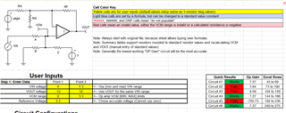
My colleague, Ron Michallick, has a great FAQ:
Within it, there is an excel that allow you to input desired I/Os and will provide different configurations/math.
In this case, I would use Circuit #1 which is less complicated:
 '
'
All the best,
Carolina
Hi Cameron,
I think there are many questions:
What is the PWM frequency and what is the minimum duty cycle?
What slew rate of +/-12V square wave do you need?
How close must the square wave's amplitude come the +/-12V supply rails?
What load has to be driven?
Are there any other circuit requirements? Like supply current, for instance?
Kai
Hey Cam,
To Kai's point, ±12V output would not work with TLV9161 (16V supply rail), I recommend moving to TLV9361 or OPA992 (40V rails).
All the best,
Carolina
Hey team,
Understood! I just threw the TLV9161 in to direct it towards the right forum. I appreciate all the feedback and am going to do some work on my end to determine what solution makes the most sense for our application.
Thanks,
Cam