This thread has been locked.

If you have a related question, please click the "Ask a related question" button in the top right corner. The newly created question will be automatically linked to this question.

LMP8481: How to measure high current with LMP8481 on high side?

Genius 15779 points
Part Number: LMP8481

Hi Experts,

Seeking your assistance on this query from Cx:
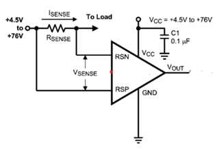

Rsense =0.03 ohm

If I try the first 0.03-ohm Rsense, 12v supply, and load current below 0.5A I get the expected LMP Vout according to the equation:
VOUT = (VRSP – VRSN) * Av ) + VREF.

Then when I changed the power supply to 42v and load current 2A I got a constant wrong Vout of 1.67v but the expected Vout is 6v the reason behind this?

Regards,
Archie A.

  • Hello Archie,

    Questions to help answer?  What was the input to VREF.  Can you show how it is driven.  What is the output for the "correct" condition?  Does the input output seem correct at 42V VCM and 0.5A?

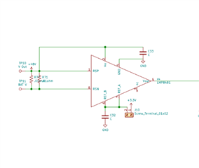
    A schematic could help to find the root cause of the issue.  

  • Hi Javier,

    Thank you for your guidance.

    VrefA and VrefB are grounded to measure positive current only. The circuit provides correct Vout and 0.2A load current when switching only on a 12v power supply. Power supply to 42V and 2A load current, then Vout got constant error value of 1.67V.

    Regards,
    Archie A.

  • ArTzy,

    What gain are you using? I was hoping to get the gain if you had given me the output when it is correct.   What is the output connected to.  Does it have a load?  Is it capacitive?  Have they tried other load currents?

  • Thanks, Javier.

    We use a 100-gain amplifier. Amplifier gain cannot be changed with external input resistors. When dc motors are powered with 12v (voltage regulator supply) and 0.2A load, get the correct Vout. If the power supply is switched to a 42V lithium battery and a 2A load with a battery discharger (inductive load), a false constant Vout of 1.67V is obtained, but it shows a correct Vsense of 0.06V.

    For further support.

    73,
    Archie A.

  • Hello Archie,

    During the inductive load does the input change drastically causing the inputs to go beyond the Absolute Max voltage ratings?  Also what is the output connected to.  The reason 1.67V sounds interesting is because it is close to 3.3V/2 like if it is clamped to that voltage.

  • Hi Javier,

    Happy Monday.

    If the supply voltage from a lithium battery is 42 volts, how can we go beyond the absolute maximum voltage? Vout is connected directly to multimeter to measure voltage. Is any relation of 3.3V Vout?

    Regards,
    Archie A.

  • Hello Archie,

    I am trying to give guidance on debug as normally the device is not at fault from my experience.  I think the output is clamped somehow.  What is your supply voltage?  Give a much information as possible as this will assist me in giving more guidance.  Is the voltage of the battery the same as the VCC pin?  When you say all you connect at the output is to a multimeter is there any resistance capacitance at the output.  The output capacitance drive capability is low on this device and you may need to add a isolation resistor.  The 3.3V is just a voltage normally in circuits and it was suspicious that the output is stuck at something similar to 3.3V/2.

  • Hi Javier,

    The supply voltage is 42V from the lithium battery. VCC and battery voltage are the same, vrefA and VrefB are grounded, and Vout is connected directly to the multimeter, and there is no other connection between them.
    What are the conditions to clamp vout?

    A 0.1-μF bypass
    The capacitor between VCC and GND pins.

    Thank you and regards,
    Archie A.

  • Hello Archie,

    I was assuming something outside of the LMP8641 device to clamp the Vout voltage.  Another attempt is to place a resistor (1kΩ) before getting to the meter.  If there is to high of a capacitive load it could impact the output.  Other than that I don't know what could be causing this.  Have they tried multiple devices?

  • Thanks, Javier.

    We're not using any capacitive load, yet my problem persists after using a 1k isolation resistor Vout clamped to Vout 1.67V. Our load is a battery discharger (resistive load).

    Any other idea to fix this?

    Regards,
    Archie A.

  • Archie,

    I will look into other ideas for this.  Let you know in a day or two.

  • Hi Javier,

    Looking forward for your response on this issue. Customer would like to share this follow up:

    We rely on TI to provide high-quality products that meet our needs, and we are disappointed that the LMP8481 has not met those expectations. We are using the LMP8481 for current sensing in our BMS (battery management system), which is a critical component of our product. We want to deliver this product within the next two weeks and to do so, we need to resolve the issue with the LMP8481 as soon as possible with TI experts.

    It will be much appreciated to solve the issue sooner. However, if the issue cannot be resolved, can you suggest another IC we can use instead?

    Regards,
    Archie A.

  • Hello Archie,

    I do not know what the root cause is for this issue with the amount of information.  Even if I suggest a part we do not know the root cause.  I do not believe the device is the issue.  Can you get the device and test it out of their system to verify?  If we place another device the issue could be continued.  

  • Hi Javier,

    Thank you for your support.

    Now the customer gave some more information on changing their power supply from 12v to 42v
    Changed the gain of the amplifier from 100% to 50% and they're sure we are using the LMP8481MM-H
    100% gain. Then how to reduce the gain from 100% to 50%?

    Their test cases are given below
    TEST CASE | TEST CASE ||
    (Rs=0.01667, VS =42 , G=50%) (Rs=0.01667, VS =12 , G=100%)

    Vout | Current(measured) | load Current Vout | Current(measured) | load Current

    1.54V 1.847630474A 2.5A 3.3V 1.979604079A 2A
    2.46V 2.951409718A 3A 4.2V 2.519496101A 2.5A
    2.84V 3.407318536A 3.5A
    3.22V 3.863227355A 4A
    4.04V 4.847030594A 5A

    For your assistance. Thank you.

    Regards,
    Archie A.

  • Hello Archie,

    Please help me understand this more clearly.  I think I need an actual schematic and layout to try to determine the issue.  Also can you have them provide data for "good data" which is below Vout of 1.54 where they expect this device to work correctly.  When I separated the data below it did not look correct.  I think there is an error in the header.

    I am not getting enough information to debug the issue.  Have they tried multiple parts?  Do they all behave the same?  Like I said before more information will help find the root cause.  Have they verified the input voltages to the LMP8481.  

  • Hi Jaiver,

    Thanks for guiding. Cx responded:

    Have they tried multiple parts?  Do they all behave the same?

    Yes, I tested the 3 lmp8481 alternately and the result is the same. I checked that the input voltages are correct.

    We are currently using the LMP8481MM-H for current sensing. In this schematic, we have connected RSP and VCC, while refA and refB are connected to the ground for positive current sensing using a shunt resistor of 0.01 ohm. When we connect a 12V power supply, we get the correct Vout corresponding to the equation with a gain of 100%. However, when we change the power supply to 42V, the Vout gets clamped into 1.7V, as the gain reduces to 50%. We are wondering what the reason behind this behavior could be.

    Thank you.

    Regards,
    Archie A.

  • Hello Archie,

    I went to the lab and verified on the LMP8481MMEVM and I do not see an issue with the Gain as VCM is changed from 7V to 42V.  Please double check there is nothing on the board or nodes clamping the nodes of the device.  

    There should not be a reason this is not working.  Have them attempted it removing components from their board.  Larger capacitance at the output.  The load of the DMM they are using.  

    Please provide them an EVM and use it the same way.  I don't have other things to investigate.  Make sure all the grounds are correct in your supplies  and measurements and there are no unknown leakage path.