This thread has been locked.

If you have a related question, please click the "Ask a related question" button in the top right corner. The newly created question will be automatically linked to this question.

PGA117: accuracy of current sense measurement

Part Number: PGA117
Other Parts Discussed in Thread: OPA325, LM7705, INA190, INA851, INA333, TINA-TI

Hello TI E2E, 

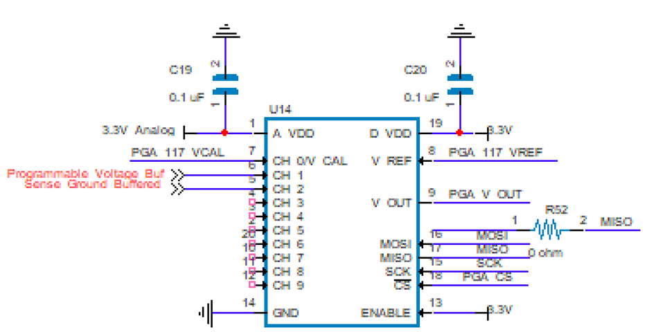
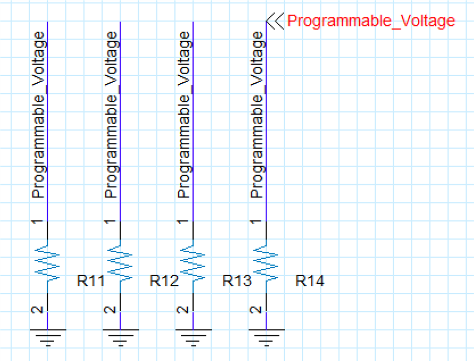
I am attaching 3 screenshots with this post for clarity. I have a programmable current source that ranges from 0.5mA to ~6A. I am trying to measure the current across a few power resistors (attached image). The resistors are about 0.5ohm. I take the voltages on both side of the sense resistor and buffer it with a unity gain closed loop buffer (OPA325) and feed it into a PGA117. The voltage on both sides of the resistors can be very close to ground. For instance, when 1mA is passing through the sense resistor, I believe the side labeled programmable voltage will be about 500 microvolts above ground and the ground side to be essentially 0V. I plan on using the programmable amplifier to magnify this signal up to 200X and calculate very small currents from it. I believe the higher current levels should not be much of a problem as long as I can accurately measure the ground voltage on the low side of the sense resistor which will be slightly above 0V. My main concern is:  

1) The programmable gain amplifier might not be able to magnify the sense resistor voltages at very low current levels or even higher ones even with large gain. My goal is to be able to control current to within 1mA steps throughout the entire range. 

Is it realistic to be able to accurately measure currents this small with this set up? If not, Do you have any design suggestions to overcome this challenge? 

Thank You. 
  • Hi Brendan,

    There are a few things I notice about this circuit. Let's start with your input stage...

    It looks like you are trying to measure a 0V input with the OPA325. I cannot see the negative supply because of the label but your positive supply (pin 5) is connected to -7.5V. I assume you simply mixed up the supply pins but even with -7.5V supply on the negative supply terminal, OPA325 has a maximum 5.5V supply which means the positive supply would have to be at most -2V. This puts a 0V measurement far out of the common mode input range of the device.

    What power supplies do you have available? Do you plan to use separate supplies for each OPA325 on your board?

    One option is to use the same bipolar supplies for both OPA325 at +/- 2.75V but that would put your 3V high-side full scale output out of the common mode range.

    Another option is to use the single 3.3V supply you have available along with the LM7705 which provides a -232mV bias as your negative supply. The LM7705 is very convenient for allowing near-ground level voltages to be measured when bipolar supplies are not available, although it does come with some switching noise at 91kHz. What is your desired measurement bandwidth?

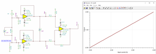
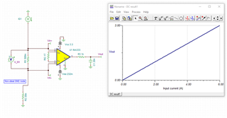
    The PGA117 is a single-ended input device with a MUX that can be switched to measure different input voltages at different times. Do you plan to measure the high-side of your shunt resistor and then switch the mux to measure the low-side, and then use post processing to realize the voltage differential? Instead, let me suggest an additional differential-to-single-ended OPA325 stage before the PGA. see below.

    I have attached this TINA simulation for your reference. Depending on your bandwidth requirements, you can add filtering capacitors at the U3 stage to reduce noise.

    The programmable gain amplifier might not be able to magnify the sense resistor voltages at very low current levels or even higher ones even with large gain

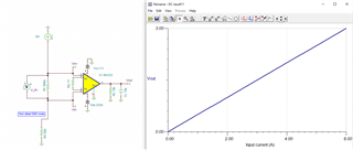
    Yes at high current levels you will need to adjust your gain setting to accommodate the output swing limitations of the PGA117, see below. That is the advantage of a PGA!

    For the low current levels keep in mind that the minimum output swing to the rail is 50mV. Your low range of 0.5mA results in an ideal input voltage of 250μV to the PGA, and the highest gain setting of 200V/V results in an output of 50mV which is right at the saturation point. Keep in mind that there are also offset voltages from the PGA and the OPA devices and other non-idealities that will combine with the ideal input voltage. You may need to increase your shunt resistor to accommodate the lower current range with less error.Current_Shunt_OPA325_PGA117.TSC

    Regards,

    Zach

  • Hi Zach, 

    Yes, I connected the bottom of the op amp to -7.5V. This can be changed because it is wrong. 

    I have a few supplies available, I have ground, 12V and -7.5V from two switch mode power supplies coming into the board. The -7.5V is swappable with a -3.3V.  I feed the 12V into a linear voltage regulator that outputs both 3.3V to a digital and analog side of the board. The analog voltage regulator supplies the positive rail of the op amps (opa117s). They all are powered from this voltage regulator with bypass caps before each component.  So, I do not plan on separating each of the OPA117 power supplies on my board.... is this ok? I assume it is as long as the voltage regulator can supply the amount of current needed by the op amps. 

    I like the idea of a small negative supply voltage. The only drawback is my ADC has an absolute maximum rating on the input pins of -0.3V. The recommended minimum is -0.1V. So I have to be careful of not putting in anything less than that to the pins. Since what it will be measuring will never be less than 0V as long as it does not have some negative gain I assume this will be ok. let me know if there is way with hardware to protect this negative voltage condition. 

    My desired bandwidth, not sure but it is pretty low. The max amount of samples that my ADC can take at that oversampling ratio is 4800 per second. I expect to be making 100 samples a second max. 

    Do you plan to measure the high-side of your shunt resistor and then switch the mux to measure the low-side, and then use post processing to realize the voltage differential? Yes. I have 8 channels on this ADC so I could do both and settle later if one is superior. 

    I am debating whether to have two constant current resistor banks, one of higher resistance that is selected when needed to measure very small currents. I might incorporate this in current or future design upon testing. 

    Thank you for that simulation. I will simulate it with TINA and most likely comment again about it soon. I was also thinking of using a instrumentation amplifier with the OPAx325 series op amps. https://en.wikipedia.org/wiki/Instrumentation_amplifier. It seems very similar to your circuit. 

    I really appreciate your help and insights. 

    Best,

    Brendan  

  • Hi Brendan,

    ADC has an absolute maximum rating on the input pins of -0.3V. The recommended minimum is -0.1V. So I have to be careful of not putting in anything less than that to the pins. Since what it will be measuring will never be less than 0V as long as it does not have some negative gain I assume this will be ok. let me know if there is way with hardware to protect this negative voltage condition. 

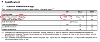
    The PGA117 is a single-supply device with a minimum output swing of 50mV, therefore it is not possible for the PGA117 to output a negative voltage to your ADC. You specified that your input current will always be positive (0.5mA-6mA) so there should not be a negative voltage input to the PGA117, however the abs max of the PGA117 is specified at 500mV below ground, so even if the OPA325 is at the negative rail (-200mV) in a fault condition, this should not cause damage to the PGA.

    My desired bandwidth, not sure but it is pretty low. The max amount of samples that my ADC can take at that oversampling ratio is 4800 per second. I expect to be making 100 samples a second max.

    100 samples per second corresponds to a bandwidth of 50Hz. At the max sampling rate your bandwidth is only 2.4kHz which still allows for plenty of output filtering to remove the switching noise at 91kHz.

    You are correct, this is a discrete implementation of an instrumentation amplifier (INA) using the three-amp method in a gain of 1 V/V. We also offer integrated INAs such as the INA333 which you may be interested in for this application.

    Current_Shunt_INA333_PGA117.TSC

    You also may be interested in our TI Precision Labs videos which cover various amplifier topics including instrumentation amplifiers: https://training.ti.com/three-amp-theory?context=1139747-1139745-1140241-1147804 

    Regards,

    Zach

  • Hi Zach,

    Thank you for that link. There are loads of good information and designs for measuring current in this situation on that link. I have one last question though about my original screenshots. I was using the opa325 to buffer the input signal into the PGA117. I don't think this is necessary and I believe the voltages ground and the top side of shunt resistor can go straight into this PGA without filtering. Would you agree? 

    Thanks for the help I will mark the chat as this resolved my issue when I hear back from you about that opa 325 being not needed. 

    Best,

    Brendan 

  • Hi Brendan,

    The PGA117 is a single-ended input device, and you are attempting to measure a differential signal. The purpose of the INA buffer stage is to convert the differential signal into a single-ended output to be measured directly by the PGA. Using the mux to measure different sides of the shunt resistor at different times will not accurately replicate the signal across the resistor. Remember the signal you are measuring is not "ideal", that is the DC current is not "perfectly" DC. Time-domain fluctuations in the signal amplitude due to noise or oscillations will cause errors in your sampled signal if the differential measurements are taken at different points in time. In theory, you certainly could skip the input stage and attempt to replicate the differential signal in post-processing but this will introduce additional errors in your circuit that may not be tolerable, especially at the lower measurement range. For best results I would recommend using the INA stage with a low-pass filter to remove out-of-bandwidth noise before the PGA.

    Regards,

    Zach

  • Thank You,

    I spent a lot of time reading that article and will probably choose an INA 851 or INA 190. 

    Best,

    Brendan 

  • please let me know if you think those are suitable choices. 

  • To clarify, I would get rid of opa 325 and pga 117 and just use those two op amps. Most likely together, since the INA 190 does not have a gain of 1 but the INA 851 does. The INA190 is a current sense op amp and INA 851 is an instrumentation amplifier with output clamping. 

  • Brendan,

    I'm not sure how you plan to use these two devices for your desired output... perhaps you have a schematic or some TINA Spice simulations that prove this concept?

    1.) The INA851 is fully-differential, meaning both the input and output are differential, whereas for your application you need a single-ended output for your ADC correct?

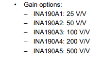
    2.) The INA190 does not have programmable or variable gain. This is a fixed-gain current-sense amplifier with different gain options depending on the part number. Additionally, the minimum gain is 25V/V which for a 3.3V supply means the maximum current you can measure is 3.3 / 25 = 132mA. I believe your input signal can be as high as 6A correct?

    Please refer to the INA333 circuit below. You can either sample the INA333 single-ended output directly, or use PGA11x as a programmable gain stage to adjust the full-scale output depending on the magnitude of the input current.

     .

    5481.Current_Shunt_INA333_PGA117.TSC

    Regards,

    Zach

  • Hi Zach, 

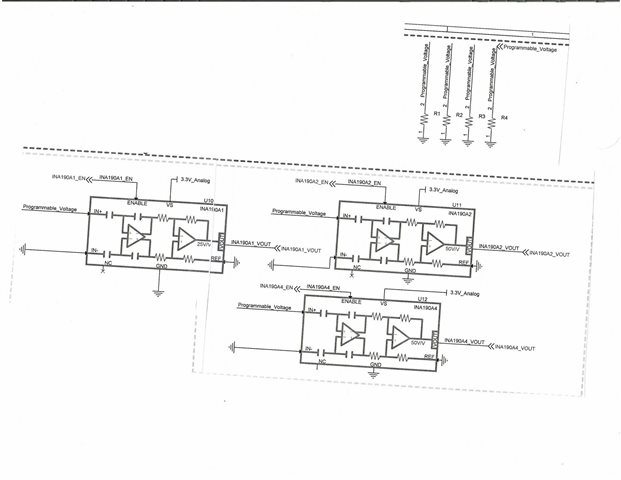
    I just got finished with the schematics that I hope will provide some clarity. I just put in the INA190s for now. There are three of them. They have 200, 50 and 25V/V gains to measure different current levels. They all sense across the same sense resistor bank .  For the larger currents I was planning on using a similar configuration with a gain of 1 or the INA851. The ADC that I am using is a sigma delta ADC with 8 channels. They can be either 4 differential or 8 single ended. The ground on that will be the same ground as the INA190s in the schematic.

    I chose the INA because they are high precision current sense op amps. If there is a similar current sense op amp with a 1V/V gain then I can use that for high currents. I was hoping that this multiple gain configuration would give me great resolution across the whole spectrum of 1mA to 6A. 

    I do not have time to simulate tonight as I have never used TINA before. Please let me know your thoughts. 

    Thank You,

    Brendan 

  • the 1V/V current sense op amps all needed I2C bus and because of other reasons in my design I would rather avoid this. 

  • Brendan,

    I recommend downloading TINA-TI and getting familiar with using it to simulate your circuits. TINA is a powerful simulation tool that will give you a lot of insight into the function and performance of your analog circuit. You can download the software here: https://www.ti.com/tool/TINA-TI#support-training.

    Once you download TINA, a great place to start is by downloading the TINA reference design of the amplifier you are evaluating for your circuit. If available, the reference design can be found in the product page under Design & Development --> Design Tools and Simulation.

    You may also refer to the TINA simulations (.TSC files) that I have attached previously in this thread as these are set up specifically for your application. These files can be a useful reference to get started simulating your circuit in TINA.

    The INA190 is a current-sense amplifier and is covered by the current sensing team. As you are no longer considering PGA117, and your circuit no longer contains anything from the precision amplifiers portfolio, I will go ahead and close this thread. If you require further support, feel free to create another post for the INA190 and the current sensing team will be able to provide support.

    Good luck with your design.

    Regards,

    Zach