This thread has been locked.

If you have a related question, please click the "Ask a related question" button in the top right corner. The newly created question will be automatically linked to this question.

LMV2011: constant current circuit

Part Number: LMV2011
Other Parts Discussed in Thread: OPA392, OPA387, OPA325, LM7705, TINA-TI

Hello ,

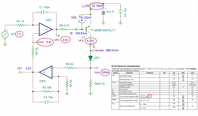
I have some questions about LMV2011

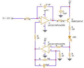
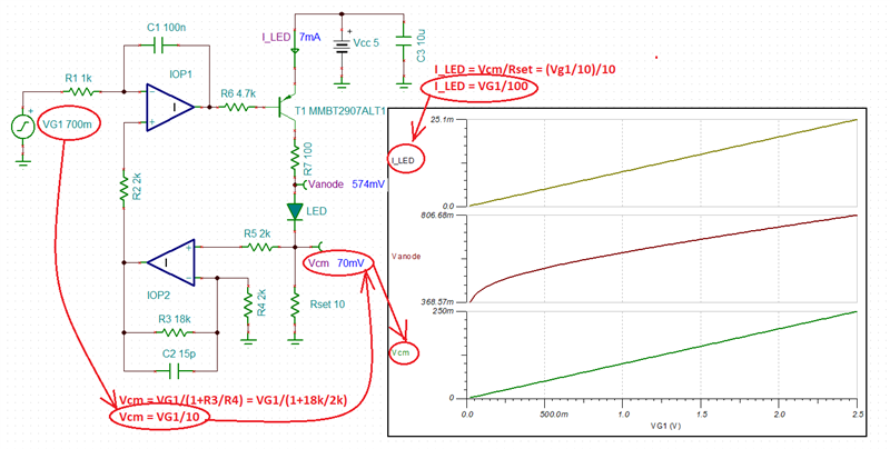
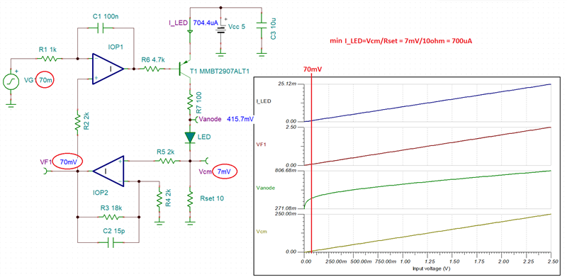
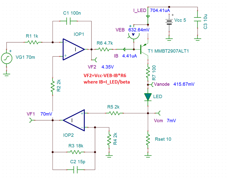
I constructed a circuit to control LED using OP AMP and PNP transistor

but there are some error on my circuit. 

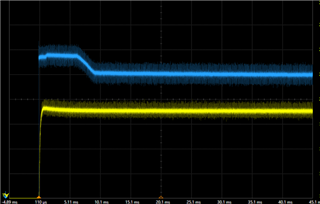
The blue one is using LMV2011 and yellow one is using other vendor's OP AMP

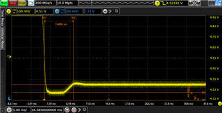
The voltage below is the measurement of the anode voltage applied to the LED, and the actual drop voltage is about 50mV ~ 100mV.

Except for the OP AMP, there is no difference in the circuit.

I wondering why the blue one (LMV2011) operating like this.

Is there anything I can check to see why the voltage is like that?

I get a lot of help from TI E2E support forums every time, thank you.

  • Please show the schematic.

    The LMV2011 does not have rail-to-rail inputs; it needs a headroom of 1.8 V to the positive supply.

  • Hello

    Here is the schematics

    I'm not fully understand "it needs a headroom of 1.8V to the positive supply."

    OP AMP input is 0V to 2.5V

    Could you explain more ? 

    Thanks,

    Rona

  • The LMV2011 does not work correctly with input voltages near the positive supply. Anyway, in this circuit, this is not a problem.

    Please measure the voltages at all inputs and outputs of the amplifiers, and check that they are not oscillating.

  • Hi Rona,

    and yellow one is using other vendor's OP AMP

    What OPAmp? Also a zero-drift chopper-OPAmp?

    Kai

  • Rona,

    The LMV2011 circuit will not work for Vout below Vout_min of 70mV - see below. 

    Since Vcm = VG1/10, this means that the minimum VG1 must be 700mV - see below.  This result in the min I_LED current of 700mV/100 or 7mA - see below simulation results using ideal op amp with Vout_min=0.  Even for ideal op am with Vout_min=in=VG1=0, I_LED=0 and the circuit stops working.

    Since no op amp output may swing on its own all the way to a negative rail, this also means that the minimum VG1=Vout_min*10, which results in the minimum LED current of Vout_min/10.

    We have some other op amps like OPA392 and OPA325 (linear) or OPA387 (chopper) with Vout_min within of 20mV, allowing minimum VG1 of 200mV or min I_LED of 2mA.  However, the only way for the min Vout and thus min VG1 range to go all the way to ground would be by biasing the negative supply pin with a negative charge pump like LM7705.

    Below I have attached Tina-TI circuit of your application.

    Rona ideal op amp circuit.TSC

  • Hello Marek Lis

    Thank you for your kind reply

    I have a question about your answer

    1. As I understand, Vout is at least 70mV, so VG1 can be 70mV too? Because the output of IOP2 is possible down to 70mV.

    2. The figure below is the measured waveform of the actual OP AMP output represented by IOP1.

    It goes from 5V to 4.25V, it drops about 70-80mV more in the beginning, then returns to 4.25V.

    What is the relationship between the Vout min you mentioned and this waveform?

  • Rona,

    See below inline answers:

    1. As I understand, Vout is at least 70mV, so VG1 can be 70mV too? Because the output of IOP2 is possible down to 70mV.

    Yes, since min VG1 is equal to min Vout, this is correct.  Thus, the minimum Vcm is 7mV and min I_LED is 700uA - see below.

    2. The figure below is the measured waveform of the actual OP AMP output represented by IOP1.

    It goes from 5V to 4.25V, it drops about 70-80mV more in the beginning, then returns to 4.25V.

    It takes time for the circuit to bias up properly (it may overshoot) but in a steady state VF2 shows a similar value - see simulation below.

    What is the relationship between the Vout min you mentioned and this waveform?

    See below:

    The maximum VG1 is limited by maximum Vcm of 3.2V and results in maximum I_LED current of 32mA - see below.