This thread has been locked.

If you have a related question, please click the "Ask a related question" button in the top right corner. The newly created question will be automatically linked to this question.

OPA187: noise from the output of OPA187

Part Number: OPA187

Hi 

 I used OPA187 as a buffer ,the input REFOUT is 2.5V, the output provide the 2.5V for a resistance bridge(350R) and a resistance 480R(see the below picture 1).

but the wave between E+ and E- always havs the low frequency noise(about 200MV PPVoltage)(see the below picture 2).

the period time for the noise ware is about 26ms. 

It is strange that the wave bewween E+ and GND , and the wave bwteen E- and GND are good , PPV for noise just below 30mV.

 I add a capacitance 2.2uf to reduce this noise ,but still have 80-100mV.

I want to know what cause this low frequency noise , and how can remove or reduce this noise.

Thanks and best regards

Kim
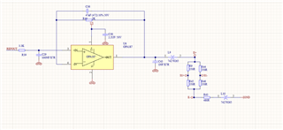
 

  • Personally, I would try replacing L9 and L10 with zero ohm resistors.  I wouldn't be at all surprised if they're causing that.

  • Actually, looking at that more closely, that looks an awful lot like it's spaced about 16.66mS apart.  Ie, 60Hz noise.

    What are you measuring the differential voltage with?

  • HI Benjamin:

       Thanks for your reply, I changed L9 and L10 to zero resistors , and the noise reduced to 70mV.

    I use the oscilloscope to measure the voltage between E+ and E-..

    And when I change R43 from 480ohm to 240ohm,  the noise become 55mV..   if R43 is Zero ,, the noise become less than 30mV.

    Do you have any other method to reduce the noise below to 30mV?

    Many thanks and best regards

    Kim

  • Hi Kim,

    Do you have any other method to reduce the noise below to 30mV?

    As Benjamin suggested, please remove L9 and L10 EMI ferrite beads. If you need attenuate the high frequency noises, I would recommend to place at Vcc rail. 

    Additional comments. 

    1. Please match the input impedance and feedback impedance (C36||R40), see the attached image (the input Ib current needs to be matched because of the chopper amplifier).

    I do not know what Vs, supply voltage you are using. 4.5Vdc is the minimum. For the buffer configuration, you will need a minimum of 5Vdc to operate for the configuration, preferably higher as simulated.  

    2. Remove C43, 1nF capacitor, which it will make the op amp unstable. 2.2uf will make the op amp unstable as well (higher capacitive load will have worst phase margin without proper feedback compensation). The op amp does not have enough phase margin when it is driving a capacitive load at the output, even at 1nF. 

    3. Please use short ground lead to measure the output signal. Please make sure that 50 Hz noise is not coupled into the op amp's output. 

    If you have additional questions, please let us know. 

    Best,

    Raymond

  • Hi Raymond:

    thanks for your relay..I removed C43, changed R40 to 3.3K, C36 to 82 nf,  change 2.2uf to 100nf,

    change L9 ,L10 to zero resistors, but the noise still more than 50mV。

    best regards

    Kim 

  • How exactly are you measuring the noise?  "With an oscilloscope" is not a complete answer.

    These amps are quite quiet - I use them all the time.  I really suspect you're seeing measurement noise.

    The noise from these parts should be WAY below the noise floor of your oscilloscope unless you've got a 1000X LNA between them.

  • Also, just to get a baseline, I would probably change R39 & R40 to zero ohm and remove C36.

    Best to get something in the ballpark and then play with values of bandwidth limiting components after that's done.

  • Hi Kim,

    I do not have explanation for the "noise" issues. As Benjamin pointed out, this is a very low noise amplifier.

    Here are some additional things that you may try. 

    1. Lower the oscilloscope's analog BW to 20MHz or lowest BW setting in the scope. 

    2. Get a differential voltage probe and measure the output of the OPA187. We need to rule out if noises are coupled from somewhere, since the noisy spikes are low frequency in nature.

    If you still observe the noisy spikes after measuring with the differential probe, you may consider to replace the op amp.  

    3. Measure the scope's noise floor as presented in "Measuring system noise" video. A typical lab should have noise floor at approx. -130dB. 

    https://training.ti.com/ti-precision-labs-op-amps-noise-measuring-system-noise?context=1139747-1139745-14685-1138803-13845

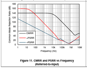
    4. OPA187 has very high CMRR and PSRR specification, especially at low frequency. Even the power supply rail is noisy, the output signals should be well attenuated. 

    Please let us know what you find. I need more clues why you are observing these issues. 

    Best,

    Raymond

  • Hi Raymond:

         thanks your your effort.. I found the noise coming from the load resistors bridge. If no connect this bridge , the noise for the output of OPA187 is just less than 20mV.

    best regards

    Kim

  • Kim,

    I still think you're seeing measurement noise.  The OPA187 has WAY less than 20mV of total noise.

  • Hi Kim, 

    I assumed that you got rid of "spiking" noise issues in the setup. I agreed with Ben that the "noise" still seems high. Use 1X probe setting instead 10X and see if it improves.  Please go through the measurement recommendation proposed in the video clip (see the previous reply). 

    I am going to close this inquiry. If you have additional questions, you may still open this thread and post additional questions. 

    Best,

    Raymond

  • Hi Raymond:

    thanks for your help.I'll will do what you suggest.

    thanks a lot  and best regards

    Kim