This thread has been locked.

If you have a related question, please click the "Ask a related question" button in the top right corner. The newly created question will be automatically linked to this question.

AMC3330: AMC3330 issue

Part Number: AMC3330

dear

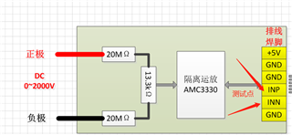
       AMC3330DWER normally operates with a common modulus of about 1.45 V for INP and INN, but for now-failed products, the common modulus of INN/INP is sometimes measured to be unstable. Sometimes it's 0, sometimes it's dynamic, sometimes it's reversible? Based on this phenomenon, I have a few questions

1. Can the chip be used in such high-pressure situations?

2. What is the output impedance of the AMC3330 differential output signal?

3. Based on our phenomenon, it seems that the output of AMC3330 will be unstable, please help to see what is the reason


any advise?thanks in advance

  • Hi Raymond,

    Can you provide o'scope screen shots of the AMC3330 to help show/explain the situation you are facing?

  • Hi Raymond,

    Any additional detail that you can provide?

  • dear tom

    The measured waveform is shown in the attachment, and the location of the tested point is shown in the figure below
    where scope1 is the waveform of INP and INN when not powered on,
    scope2 is the waveform of INP and INN at power-on (where yellow is INP and green is INN) - the INN signal is 0V at this time, and it is faulty
    scope4 is the waveform of INP and INN at power-on (where yellow is INP and green is INN), at which time ---the INN and INP signals are normal,
    At present, it is suspected that the INN output may be abnormal and may not be a permanent failure, so we are willing to ask your experts to help analyze it from the perspective of internal design/use environment of the AMC3330

    thanks

  • Hi Raymond,

    Do you have an actual schematic that you can share?  The INN of the AMC3330 is normally referenced back to HGND (pin 8) to keep the common mode voltage within the specified limits.