This thread has been locked.

If you have a related question, please click the "Ask a related question" button in the top right corner. The newly created question will be automatically linked to this question.

OPA818: TIA OPAmp part selection

Part Number: OPA818
Other Parts Discussed in Thread: OPA656, , OPA657

Hi,

I'm trying to understand the principle of the TIA OPAmp selection. 

I used tha TIA_Claculator and input the requirements:

( TIA output bandwitdh = 1MHz, Gain resistor = 1.5Mohm, C_APD_12053-10_Terminal = 15pF, C_TOT_OPA656 = 3.5pF, C_pcb = 0.3pF )

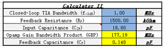
And I guess it uses the same fomula:

So the required GBP of the OPAmp should be large than around 180MHz.

For this requiment, there are lot numbers of OPAmp could be selected.

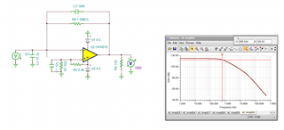
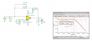
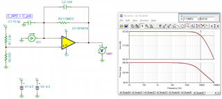
I simulated with OPA656 and OPA818. Both of them satisfied the stability and BW with same gain resistor (and same compenation capacitor).

OPA656 - Phase margin 61°

OPA818 - Phase margin 84°

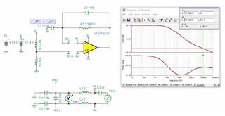
OPA656 bandwidth 1.33M

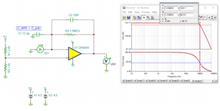
OPA818 bandwidth 1.13M

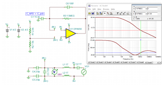
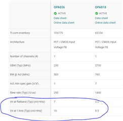
And compared the noise characterstic, the OPA818 is a llittle better than OPA656

So my question is - 

1) For my requirement, to get best performance (low noise, stable), the OPA818 is better, is it right? Or is there other part you would recommend?

2) Are there any other things/parameters I should take into consideration?

Thanks and Best regards.

  • That is a pretty thorough review Follin,

    The OPA818 is an upgrade to the decompensated OPA657, so that would be the closer part to compare to. But, since the OPA818 is the newer version, probably will be the better solution, 

    Also, unless you are buying special low C feedback R, the typ parasitic on that 1.5Mohm would be aroud 0.18pF, might try that in simulation. 

  • Yes, if I take your circuit 0.18pF feedback C, it is still stable but the feedback pole is 560kHz, so 1MHz does not appear to be achievable. Not because of the op amp - it can do 4MHz closed loop if you can get the feedback C down to .037pF. 

    One option is what is called a Tee network, split the feedback Gain into and Rf and voltage gain stage, such as this, 

    Yes, now 1.9MHz F-3dB, you have room here to add feedback C to control the BW. 

    And this file, in TINA V9

    opa818_Zt test with tee network.TSC

  • Hi Michale,

    Many thanks! I have very limited space so I might decrease the feedback resistor. 

    And then I have another question with respect to the feedback resistor value. 

    If I use a large one:

       1.The bandwidth is limited, and it seems more easily to get interfenced.

       2.And if I want to keep the TIA bandwidth, I shall use the small feedback resistor, for instance 0.5pF. Then the noise above the frequency 1/(2 x pi x Rf x Cf) will be amplified by a factor of C_TOT/Cf, for C_TOT=15pF it will be 30.

    If I use a small one:

       The SNR for the TIA stage seems to decreased. 

    And for APD signal amplification, the APD bias voltage also controls the gain, which means we might not have a specific gain requirement for value of feedback resistor (Rf). 

    So is there a way to pick the right value of the feedback resistor reasonably?Or it's just like a "test and change" thing?

    I know it's a out of the component issue range here, but I can recall that you or Kai have a lot experience in APD/PD TIA circuit design. So it will be very appreciated if you can let me know a bit moreGrinning  Thanks again!

  • Hello Follin,

      Thank you for looking over TIA information spanning e2e, calculator, and app notes!

       Your understanding is correct for large/small feedback resistor case. Do you happen to know what your input current range will be for your design? If it is a wide range, maybe an integrated TIA with gain switches might be a better solution. This will decrease space since you mentioned you have size constraints, and our integrated TIAs have additional functions such as ambient light cancellation or/and gain switches.

    Thank you,

    Sima

  • Hi Sima,

    Unfortunately I do not have the current range for my design. Acctually my idea is to amplify it as large as possible, and for dynamic range (large current) I think the bias voltage of APD would handle the gain. 

    Thanks for your reply!