This thread has been locked.

If you have a related question, please click the "Ask a related question" button in the top right corner. The newly created question will be automatically linked to this question.

Suggest me best circuit option for design amplifier with tiny OP-AMP for low amplitude(20mv) and low frequency signals(15Hz)

Other Parts Discussed in Thread: LM7705, OPA192, OPA392

Hello all,

Input pulse SPEC:

Pluse width:2ms

Period:100ms

Amplitude :20mV

i am trying to design a non inverting amplifier with filter . My input signal coming with very low voltage and frequency (20mv and 15Hz). And i need to amplify it and make the signal high for indicating it is false case IN DESIGN application (Planning to use Latch).

I designed a op amp(Gain=151 & vcc=1.8V) with BPF(Fl=2hz and Fh=15hz). My fear is that it may amplify the small noise glitch also along with desired signals.pls make comments on it. And welcoming if changes are required.

Any i cause any pulse width detection method to detect my desired pulse and after i will do the amplification. So any method is there to detect the pulse width of 2ms with period of 100ms

Could to pls suggest me best part and circuit example for my design .

Thanks 

Vinay

  • *Any method for pulse width detection method to detect my desired pulse and after i will do the amplification. So any method is there to detect the pulse width of 2ms with period of 100ms*

  • Hi Vinay,

    what is the source of your signal?

    Kai

  • Source is a AC pulse signal having 100ms Time period with 2ms pulse width, Having amplitude of 20ms

  • HI Vinay,

    The post above mentions that the signal interest is a ~20mV amplitude pulse, with 2ms width and 100ms period; and you are working to design a non-inverting amplifier/filter stage:

    I designed a op amp(Gain=151 & vcc=1.8V) with BPF(Fl=2hz and Fh=15hz). My fear is that it may amplify the small noise glitch also along with desired signals.pls make comments on it. And welcoming if changes are require

    We need to better understand the application requirements prior suggesting an amplifier and/or circuit:

    What kind of sensor or source circuit is producing the pulse signal of interest?

     I assume you are you trying to amplify the 20mV pulse signal through the non-inverting bandpass filter/gain stage.  Is this correct?  The post describes a pulse with 100mS period (10-Hz) and 10mS pulse width; but the title mentions a 15-Hz signal.   What is the expected pulse width range and period/frequency variation?

    Please clarify, Is the circuit powered with a unipolar supply of +1.8V ?  Please note that if the input signal is a ~20mV pulse and the desired gain stage has a gain of ~151V/V, this corresponds to an output voltage greater than >3V, outside the supply range. Please clarify the gain and/or supply requirement.

    Regarding the small signal noise glitch you wish to eliminate: What is the amplitude and frequency range of this noise glitch that you don't want to amplify with the signal? 

    Can you please post the schematic and sensor of the circuit you have designed?

    Thank you and Regards,

    Luis

  • Hi Luis,

    Thanks for response,

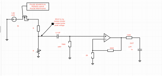
    1)There is no sensor, signal pulse is from coming from a resistor divider network, the source is LDO 1.8V

    Based on LOAD falling on one of the resistor in resistor divider, The amplitude is varying,, so the amplitude will vary according to the load falling on resistor divider network. the enabling period of LDO through Mosfet is 100ms and pulse width 2ms. so the voltage of least case is 20mV,

    Hope can get an idea by this circuit draft.

    Thanks,

    Vinay

  • HI Vinay,

    I am looking into this circuit, I expect to get back to you shortly,  by Friday AM US time.

    Thank you and Kind Regards,

    Luis

  • Hi Vinay,

    I would do it this way:

    vinay_opa192.TSC

    V2 is provided by the LM7705. But you can also use another small negative supply voltage, like -5V for instance.

    Kai

  • Hi Vinay,

    how does the circuit work?

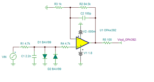
    R1 and C1 provide a simple passive glitch filter since you mentioned that your signal is superimposed by a "small noise glitch". A passive filter in front of an amplifier is the best way to handle unwanted "noise glitches" because once a "noise glitch" has entered an OPAmp, it may be harder to suppress it.

    The time constant R1 x C1 determines how much noise glitch suppression you can achieve. But at the same time it also affects your wanted signal. I have set the time constant of R1 and C1 such that the square wave peak begins to show rounded edges as you can see in the simulation.

    R1 is set low enough to not add too much resistor noise.

    D1 and D2 provide a diode clamping and protect the +input of OPA192 against unforseen overvoltage conditions. R4 limits the resisual input current into the OPA192 input during overvoltage conditions: With a turn-on voltage of 0.7V the current into the input of OPA192 is limited to below 150µA.

    The feedback resistors provide a gain of 151V/V. C2 adds some low pass filtering and improves the stability of circuit by enhancing the phase margin.

    R5 isolates the OPAmp output from capacitive loads and also stabilizes the OPAmp.

    Because no OPAmp can go with the output voltage all the way down to 0V in a single supplied circuit, you need some small negative supply voltage. The -0.23V coming from the LM7705 is already enough to make the OPA192 properly work. But you can also take another negative supply voltage.

    The OPA192 was chosen because it shows a very low input offset voltage, a very low input noise voltage, is rail-to-rail capable at the input and output and is fast enough to allow a gain of 151V/V.

    Kai

  • Thank you Kai,

    HI Vinay,

    The circuit that Kai has proposed with the precision OPA192 will work very well providing gain of +150V/V, producing a ~3V output for a 20mV pulse while powered with a +5V supply and using the LM7705 to generate the negative -0.232V supply.  This is a very good approach.

    If you are restricted in the design to use the LDO +1.8V supply , you could use the same circuit implemented with the OPA392, while reducing the gain to ~85V/V, producing a ~+1.7V output for a 20mV input pulse. The OPA392 is also a high-precision, low noise amplifier that can work with a total supply V(+) - V(-) in the range of +1.7V to +5.5V.

    As Kai has explained, the caveat is no op-amp can reach 0V while powered with a single positive supply, and you would need some small negative supply voltage. Below is the same circuit, modified with the OPA392, lowering the gain. 

    Thank you and Regards,

    Luis

  • Hi kai & luis,

    Thanks for the long reply and clear explanation with simulation.

    And the circuit suggested is also good ,but the i need to amplify only frequency  500Hz signals. so i planning to implement Band pass filter along with suggested design by you.

    Is it work for Band pass filter implementation?

    Thanks  

    Vinay Varikooti 

  • Hi,

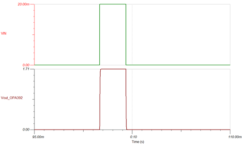
    This is the simulation result, which i got for suggested circuit. But i need to detect & amplify only during the pulse width 2ms(500Hz) with pulse period 100ms. as shown in graph.  So i was planning to implement the BPF(Fl=500-30 Fh=500+50), to filter out the noise pulses out of this bandwidth.

    Any other suggestions also appreciated,Thank you

  • Hi Vinay,

    But i need to detect & amplify only during the pulse width 2ms(500Hz) with pulse period 100ms.

    a 2ms pulse with a pulse period of 100ms is no "500Hz signal". A 500Hz signal is a sine wave lasting infinitely long and which does not have a start or an end. But your signal is far away from being an infinitely long lasting sine wave. It contains lots of far reaching harmonics and a DC component which all become differently affected by the bandpass filter in terms of attenuation and phase delay. So, when you run your complex signal through a band pass filter, you will see lots of transient phenomena like ringing, overshootings and undershootings.

    Your signal is defined in the time domain and you should not use tools which are only perfectly working in the frequency domain. This will not go together. If you don't want nasty transient phenomena, then you should use very mild filtering allowing your signal not to become all too much distorted. That's why I have omitted any high pass filtering (AC coupling) and only used rather mild low pass filtering.

    Kai

  • HI Vinay,

    I agree with Kai.  The 2ms duration pulse has a fundamental frequency of ~500-Hz, but the pulse signal contains a number of high-frequency harmonics. In addition, realizable filters have associated phase delay, and do not have an infinitely steep transition between passband and stopband.  The simplest approach is to use a low-pass filter with relative higher bandwidth to allow the 2mS pulse and a number of harmonics of the pulse signal through. For example, a low pass filter with >5-kHz corner will allow the fundamental and at least ~10 harmonics, while filtering any higher frequency noise.

    If you require a low-pass filter with a steeper transition between passband, and stopband, you could use a second-order (or higher order by adding stages) Bessel low-pass filter, offering maximally flat delay; but again, the frequency bandwidth of the low-pass filter must be wide enough to allow the pulse fundamental frequency and a number of the higher frequency harmonics. 

    Thank you and Regards,

    Luis  

  • Hi Vinay,

    do you want to filter the signal only prophylactically or do you urgently need to suppress some unwanted noise or glitch? If so, can you show a scope plot?

    Kai

  • Vinay,

    Please let us know information the signal noise glitch you wish to eliminate: What is the amplitude and frequency range of this noise glitch that you need to attenuate with the filter; and/or let us know what is the frequency and level of attenuation required in the stopband.

    Best Regards,

    Luis