This thread has been locked.

If you have a related question, please click the "Ask a related question" button in the top right corner. The newly created question will be automatically linked to this question.

INA180-Q1: Please check if GAIN4 is correct when applying current sensing and resistance

Part Number: INA180-Q1
Other Parts Discussed in Thread: INA180

Hello Team,

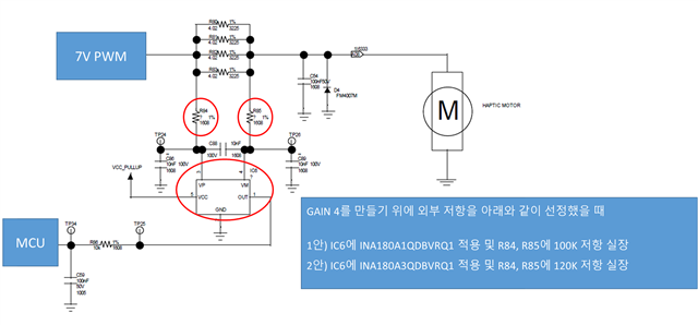
Could you please check if GAIN4 is correct when applying current sensing and resistance 

(now they are setting with Gain 4)

INA180A1QDBVRQ1 (IC6 apply): R84, R85 100K resistance 

INA180A3QDBVRQ1(IC6 apply): R84, R85 120K resistance

<Circuit>
  • Jimmy,

    I don't understand the question here. Are they attempting to alter the gain of the device here, or are they installing R84 and R85 as protection resistors?

    A few issues I see in the schematic you've presented:

    - They do not have a decoupling capacitor on the Vs pin. This is best practices and should be present on the circuit

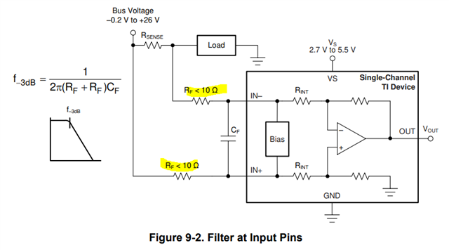
    - If R84 and R85 are truly 100k-120k, the device will most likely not function properly. Have a look at this excerpt from the datasheet:

    For these values, the injected gain error would be 

    INA180A1@100k: 98.8%

    INA180A3@120k: 99.17%

    In essence, these values would be unusable due to these resistors. Placement of these resistors fundamentally changes the gain of the device. They need to be held to <10Ω for the INA180:

    If they are attempting to alter the GAIN of the device, this is also not recommended as the internal resistors of the device are not trimmed to absolute values. They are trimmed to each other, and as a result the absolute values may fluctuate by up to +/-20%.