This thread has been locked.

If you have a related question, please click the "Ask a related question" button in the top right corner. The newly created question will be automatically linked to this question.

TLV1811: pull low resistor

Part Number: TLV1811
Other Parts Discussed in Thread: TLV1821, UCC256404, TLV3201

Hi team,

we want to use TLV1811 to pull low below 0.9 threshold,

but there's other divider resistor on the output of TLV1811,

we need to know the internal pull-low resistor to make sure the output voltage will be below 0.9V

  • Hello Fred,

    We do not have a pulldown "resistor" the output is a MOSFET (as shown on the front page block diagram).

    The output should swing within millivolts, depending on the load current.

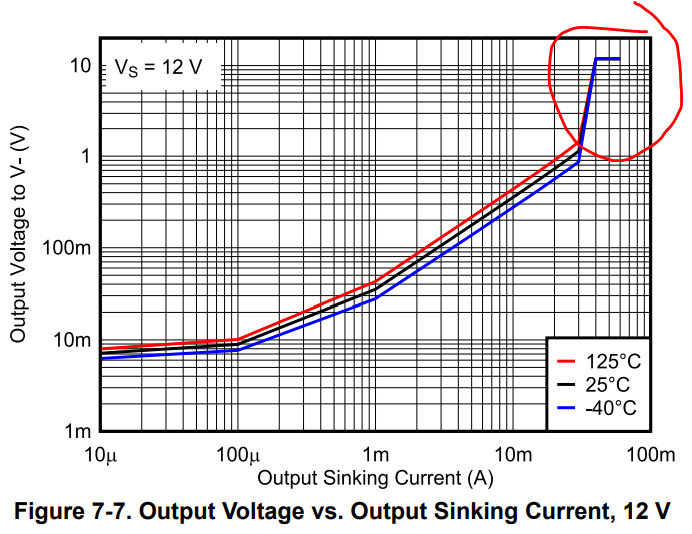
    You need to look at the "Output Voltage vs. Output Sinking Current," curves on pages 10 and 11. These graphs show the output "low" voltage versus the load current.

    Does "0.9 threshold"  mean 0.9V, or 0.9*Vs?

    Looking at the 5V graph, you would need to sink almost 20mA to reach 0.9V on the output.

    Can you please provide a schematic and/or measurements?

  • Hi Paul,

    it's just an ideal for customer now, the Vs(RVCC) is 13V here, we should refer to 12V curve.

    since output was around 5V(BLK) originally,

    does this mean the current will start to sink from around 30mA and drop to below 20mA when output is below 0.9V, and eventually it will drop to 0V, right?

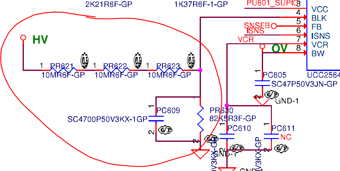
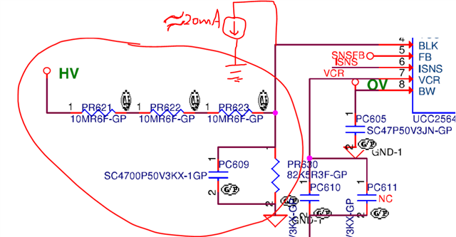
    I just want to make sure it will sink below 0.9V threshold eventually since there's already a divider resistor there. please see second picture

  • Hello Fred,

    The region you have circled is the current limiting area. When the output is shorted, the current is limited to about 35mA. This is not a normal operating condition.

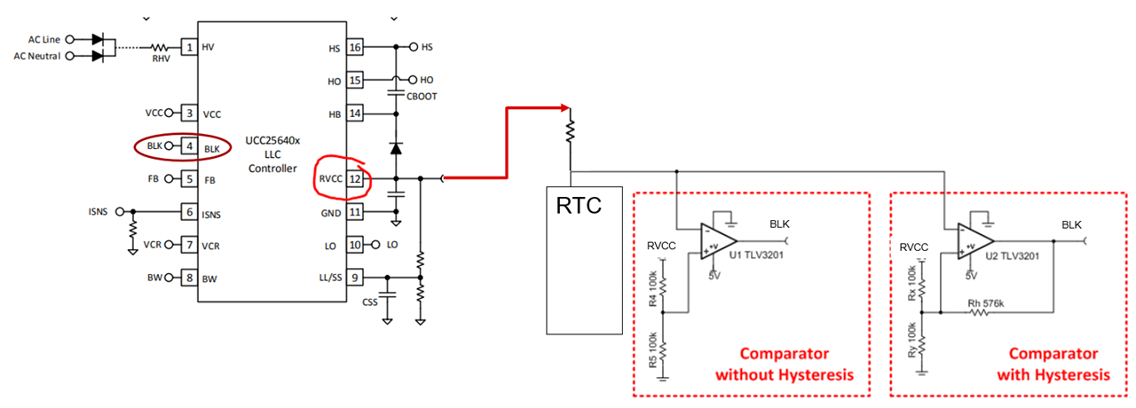
    Are they trying to tie two outputs together? As shown in the schematic?

    If so, the TLV1811 is a push-pull output, that can both sink and source. You cannot tie two push-pull outputs together as they will fight and short each other out.

    If you need to tie two outputs together to "OR" the output, then you need the open drain outputs. The open drain version is the TLV1821, and they will also need a pull-up resistor.

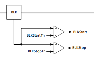
    What are the logic levels for the BLK input?

  • no Paul,

    we just need something to pull low the BLK pin which has a 0.9V threshold. we want to sink it  below 0.9V to off the UCC256404 IC.

    but the thing is there's already a divider resistor connect to BLK pin to create original 5V. so I just wonder if I should concern these divider resistor?

    there's no two push-pull scenario, there's only two comparator input inside the BLK pin,

    it's very simple case, please don't get confused.

    just help consider the divider resistor, thanks 

  • Hi Fred,

    Thanks for the follow up. I am still having a bit of trouble understanding your circuit. The previous schematic you sent showed two TLV3201's with the output connected to the BLK pins. This is probably why Paul thought it was two push pull outputs tied to the same pin. As Paul mentioned, if your concern is that when the output of the comparator is LOW, it is less than 0.9V, then you need to make sure it is sinking less than ~20 mA. 

  • Hi Nguyen,

    I'm really confused right now.

    let me put this again, please ignore all the schematic before, like I said it's not ready.

    just focus on this one below, if TLV1811 output connect to BLK which already has a divider resistor from HV(264V) and a 4.7nF cap and don't care about BLK, it's a gate, another comparator input.

    what do I need to make sure about divider  to ensure my output will be pull low to below 0.9V?

     the sink current start from TLV1811 is around 20mA when output was 5V originally, right?

  • Hi Fred,

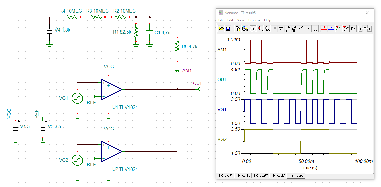
    like this?

    3806.fred_tlv1821.TSC

    With OUT = BLK.

    Kai

  • Hi KAi,

    really appreciate a lot for your simulation, that tells everything, but still a little different from what I want.

     would help me run it again but this time eliminate one TLV1821, and change the other one to TLV1811? I only need one TLV1811

    and also eliminate R5  4.7kohm? there's no 4.7k in the original schematic. just short it to BLK directly.

  • Fred

    Kai provided his simulation file.  I assume you were able to make the changes and re-run the simulation as you desired.  We will be on out on holiday on Monday but if you have further questions, please let us know and we will respond on tuesday.

    Chuck

  • Hi Fred,

    without R5 a high short circuit current is flowing out of C1 and into the output of comparator during a brief period when the output of comparator is toggling from high to low. This would be bad design practise because this short circuit current will cause lots of ground noise and ground bounce and can destabilize parts of the circuit. And if the short circuit events happen again and again or even periodically they can damage the comparator.

    With R5 = 4k7 the current is limited to about 1mA (as you can see from the simulation) and is following the recommendation given in section 8.4.2.2 of datasheet. You may decrease R5 down to 1k. But this will increase the output current up to 4...5mA and can already result in unacceptable ground noise and ground noise.

    Kai

  • Hi KAi,

    the R5 won't affect the voltage level of the original divider ( when comparator output high), right?

    if it doesn't, then I can add it to prevent ground noise like you said

  • Fred,

    For output high, the comparator will toggle to 5V as shown in his tina sim.

  • Hi Chi, Kai,

    we're going to show this design to customer two days later,

    we don't want the comparator's output affect original voltage unless the comparator output logic is 0,

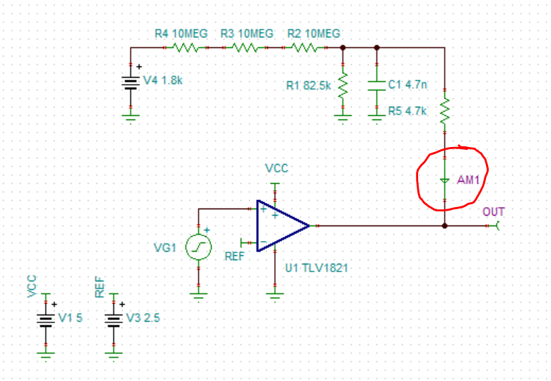
    so would you help me insert a regular diode at red circle and run the simulation to probe the output and the anode of the diode?

    we want to check the voltage level .

    BTW, is there a chance we can have a meeting later today around 5~6pm your time zone?

  • Fred,

    Since we are taking this offline, I will be closing this thread.