This thread has been locked.

If you have a related question, please click the "Ask a related question" button in the top right corner. The newly created question will be automatically linked to this question.

OPA992: Suggestion about provide bias for TIA

Part Number: OPA992
Other Parts Discussed in Thread: ADS7961, , LM7705, OPA2810, OPA355

For our design, we have 16 channels and connect to ADS7961, as this picture:

I read here design for photodiode TIA:

https://www.ti.com/lit/pdf/tidu535

Regarding here bias(offset) network:

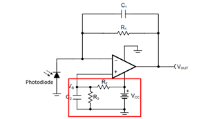
Since there would be 16 (R2, R3 and C2) when 16 channels,

we'd like to reduce amount of R2, R3 and C2.

My idea as this picture:

Set 1 bias network, through a buffer, power plane for every channel.

Is this solution bad?

  • Hi Dewei,

    of course, you can do so, allthough you only save two resistors per each TIA? But in any case you would need to isolate the output of OPA992 from the capacitive loads presented by the decoupling caps at the +inputs of TIAs. An advantage of this method is that all TIAs see exactly the same bias voltage. A disadvantage is that the very sensitive and vulnerable +input of TIA does not see a short wiring directly and closest to the OPAmp any longer but a largely pulled apart wiring being extended over 16 channels. This makes the bias line very sensitive to EMI and a simple decoupling cap may not be enough to gurantee proper operation. You would need to add a resistor at the +input of each TIA again to form a low pass filter in combination with the decoupling cap at the +input.

    But there's still another issue. If you want highest precision, then you should run the photodetectors with zero bias. For a high precision photodetector all the specifications are usually given at zero bias. Going away from zero bias will introduce additional errors. Because of that I would connect the +input of each TIA directly at the OPAmp to signal ground (which is the best way to minimize EMI anyway) and would power the TIAs (and eventually the following OPAmps) with a small negative supply voltage of some hundreds of mV. The LM7705 may be useful.

    Kai 

  • Hi @Kai Klaas69:

    Sorry that reply too late.

    I'm summing up:

    tidu535 said op-amp needs a little positive bias at V+ because if Vi too small to across GND, then OPA will “saturate” near its negative power supply.

    Maybe I can overcome this problem when I supplied OPA with dual rail(Vs+/Vs-).

    Or If I still want implement TIA with single-end, add LM7705 is good choice as you mentioned

    Do you recommend provide negative bias for Vs- of OPA and negative bias of photodiode with "voltage reference", not recommend "Voltage regulator"?

  • Hi Dewei,

    since I do not know your circuit, there's no simple answer. Keep in mind though, that the ADS7961 only withstands a maximum negative input voltage of -0.3V. So, a negative supply voltage for the OPA2810 and OPA992 of way more than -0.232V (LM7705) may not be a good idea.

    Kai

  • Hi Kai Klass69:

    I add circuit.

    Regarding integrator and LPF, I've not decided value of resistor and capacitor yet.

    I thought my design, OPA355 can't output negative voltage.

    Add -2.5V to Vs- of OPA2810 and OPA355 is just to satisfy minimum Vs rail of OPA2810 (4.75V).

  • Hello Dewei,

    The OPA355 does not allow 7.5V supply. 5V - [-2.5] = 7.5V

  • Hi @Ron Michallick

    Thank you for your notice.

    I'll connect Vs+ of OPA355 to +4.5V.