Hi.
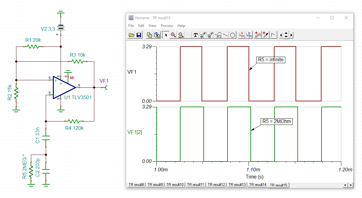
I built a schematic. I need frequency equation of the circuit? What it is? Thanks
.
This thread has been locked.
If you have a related question, please click the "Ask a related question" button in the top right corner. The newly created question will be automatically linked to this question.
Hi.
I built a schematic. I need frequency equation of the circuit? What it is? Thanks
.
Hello,
Thanks for reaching out. There is an example of a relaxation oscillator circuit in section 8.2.1 of the TLV3501 datasheet. We also have this app note Relaxation oscillator circuit.
Thanks Chi.
I know the equations in these sources. but I could not understand the effect of C2 and R5 in the circuit on mat.equation.
Hi,
Sorry I misunderstood your question. I would expect that C2 is now in series with C1 so the total capacitance would need to include both C1 and C2 in the oscillation timing equation. R5 is now also in the resistor divider with R4 so that needs to be included as well.
Hi,
as the simulation shows, R5 mainly influences the duty cycle of square wave but has nearly no influence on its frequency:

R5 is merely added to improve the symmetry of the square wave. To find the frequency of square wave put the sum of C2 and C1 (33.2nF) the series capacitance of C1 and C2 (199pF) into the formula. The influence of R5 on the frequency is way smaller than the manufacturing tolerances and drifts of C1 and C2 and may be neglected.
Kai
Hi.
I understood R5 thanks for your comment.
But I think C1 and C2 are series. Thats why total capacitance is about 199pF. am I wrong?
thank you Kai.
I hope that helps you with your design elektroboard. Let us know if you have any more questions.
Hi Elektro,
Using the equations in the app note, I have 0.77 = 2.3 e^(-t/(2*120k * 199pF)) which works out to be t = 2 * 120k * 199pF * ln(0.77/2.3) = ~52us which roughly matches Kai's sim.